STK14C88-3 查看數據表(PDF) - Cypress Semiconductor
零件编号
产品描述 (功能)
生产厂家
STK14C88-3 Datasheet PDF : 17 Pages
| |||
STK14C88-3
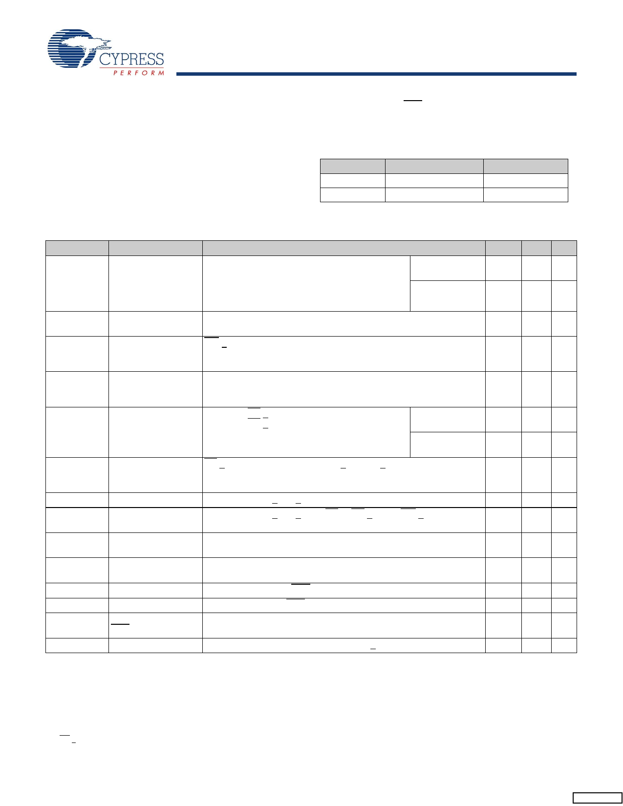
Maximum Ratings
Exceeding maximum ratings may shorten the useful life of the
device. These user guidelines are not tested.
Storage Temperature ................................. –65°C to +150°C
Temperature under bias.............................. –55°C to +125°C
Supply Voltage on VCC Relative to GND ..........–0.5V to 7.0V
Voltage on Input Relative to Vss............ –0.6V to VCC + 0.5V
Voltage on DQ0-7 or HSB .......................–0.5V to Vcc + 0.5V
Power Dissipation ......................................................... 1.0W
DC output Current (1 output at a time, 1s duration) .... 15 mA
Operating Range
Range
Commercial
Industrial
Ambient Temperature
0°C to +70°C
-40°C to +85°C
VCC
3.0V to 3.6V
3.0V to 3.6V
DC Electrical Characteristics
Over the operating range (VCC = 3.0V to 3.6V) [6]
Parameter
Description
Test Conditions
ICC1
Average VCC Current tRC = 35 ns
Commercial
tRC = 45 ns
Dependent on output loading and cycle rate. Values
obtained without output loads.
Industrial
IOUT = 0 mA.
ICC2
Average VCC Current All Inputs Do Not Care, VCC = Max
during STORE
Average current for duration tSTORE
ICC3
Average VCC Current WE > (VCC – 0.2V). All other inputs cycling.
at tRC= 200 ns, 5V, Dependent on output loading and cycle rate. Values obtained without
25°C Typical
output loads.
ICC4
ISB1[7]
Average VCAP Current All Inputs Do Not Care, VCC = Max
during AutoStore
Average current for duration tSTORE
Cycle
Average VCC Current tRC=35ns, CE > VIH
(Standby, Cycling TTL tRC=45ns, CE > VIH
Input Levels)
Commercial
Industrial
ISB2[7]
IIX
IOZ
VIH
VCC Standby Current CE > (VCC – 0.2V). All others VIN < 0.2V or > (VCC – 0.2V).
(Standby, Stable
CMOS Input Levels)
Input Leakage Current VCC = Max, VSS < VIN < VCC
Off State Output
Leakage Current
VCC = Max, VSS < VIN < VCC, CE or OE > VIH or WE < VIL
Input HIGH Voltage
VIL
Input LOW Voltage
VOH
VOL
VBL
VCAP
Output HIGH Voltage
Output LOW Voltage
Logic ‘0’ Voltage on
HSB output
IOUT = –4 mA except HSB
IOUT = 8 mA except HSB
IOUT = 3 mA
Storage Capacitor Between VCAP pin and Vss, 68 to 220uF +20%, 4.7V rated.
Min
-1
-1
2.2
VSS –
0.5
2.4
54
Max Unit
50 mA
42 mA
52 mA
44 mA
3 mA
9 mA
2 mA
18 mA
16
19 mA
17
1 mA
+1 μA
+1 μA
VCC + V
0.5
0.8 V
V
0.4 V
0.4 V
264 uF
Notes
6. VCC reference levels throughout this data sheet refer to VCC if that is where the power supply connection is made, or VCAP if VCC is connected to ground.
7. CE > VIH will not produce standby current levels until any nonvolatile cycle in progress has timed out.
Document Number: 001-50592 Rev. **
Page 7 of 17
[+] Feedback
Share Link: 