HIP4020 查看數據表(PDF) - Intersil
零件编号
产品描述 (功能)
生产厂家
HIP4020 Datasheet PDF : 9 Pages
| |||
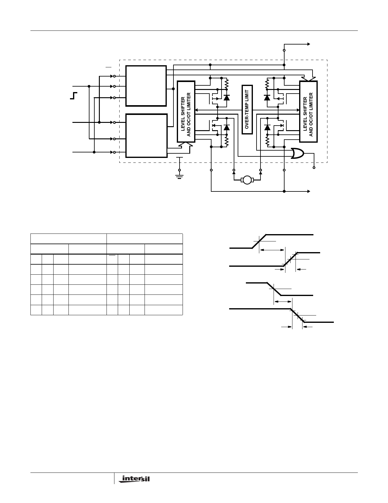
HIP4020
V+
VDD
BRAKE
ON
OFF
DIRECTION
ENABLE
B1
B2
ENB
A1
A2
ENA
CONTROL
LOGIC B
CONTROL
LOGIC A
Q1
D1
D2
Q2
Q3
D3
D4
Q4
VSS
VSSA OUTA
OUTB
VSSB
ILF
(LOGIC
LOAD
GROUND)
V-
FIGURE 1. TYPICAL MOTOR CONTROL APPLICATION CIRCUIT SHOWING DIRECTIONAL AND BRAKING CONTROL
TRUTH TABLE
SWITCH DRIVER A
SWITCH DRIVER B
INPUTS
OUTPUT
INPUTS
OUTPUT
A1 A2 ENA
OUTA
B1 B2 ENB
OUTB
HL H
OH
LL H
OH
LL H
OL
HL H
OL
HH H
OL
LH H
OL
LH H
OL
HH H
OL
XX L
Z
XX L
Z
L = Low logic level; H = High logic level
Z = High Impedance (off state)
OH = Output High (sourcing current to the output terminal)
OL = Output Low (sinking current from the output terminal)
X = Don’t Care
FIGURE 2.
VEN
VOUT
50%
tPLH
10%
90%
50%
tr
VEN
VOUT
50%
tPHL
10%
tf
50%
90%
SWITCHING WAVEFORMS
Application
The HIP4020 is designed to detect load current feedback
from sampling resistors of low value in the source
connections of the output drivers to VDD, VSSA and VSSB
(See Figure 1). When the sink or source current at OUTA or
OUTB exceeds the preset OC (Overcurrent) limiting value of
550mA typical, the current is held at the limiting value. If the
OT (Over-Temperature) Shutdown Protection limit is
exceeded, temperature sensing BiMOS circuits limit the
junction temperature to 150°C typical.
The circuit of Figure 1 shows the Full H-Switch in a small motor-
drive application. The left (A) and right (B) H-Switch’s are
controlled from the A and B inputs via the A and B CONTROL
LOGIC to the MOS output transistors Q1, Q2, Q3 and Q4. The
circuit is intended to safely start, stop, and control rotational
direction for a motor requiring no more than 0.5A of supply
current. The stop function includes a Dynamic Braking feature.
With the ENABLE Inputs Low, the MOS transistors Q1 and Q3
are OFF; which cuts-off supply current to OUTA and OUTB.
With the BRAKE terminal Low and ENABLE Inputs High, either
Q1 and Q4 or Q3 and Q2 will be driven into conduction by the
5
FN3976.3
December 20, 2005
Share Link: 