DMS-20LCD жҹҘзңӢж•ёж“ҡиЎЁпјҲPDFпјү - Murata Power Solutions
йӣ¶д»¶зј–еҸ·
дә§е“ҒжҸҸиҝ° (еҠҹиғҪ)
з”ҹдә§еҺӮ家
DMS-20LCD Datasheet PDF : 6 Pages
| |||
point location pins should be left open. For 5V-powered models, the
decimal location pins are TTL compatible and may be hard wired as
described above or driven with 5V TTL logic gates.
4. BACKLIGHT (Pin 9) Function: Grounding pin 9 (i.e. connecting it to
pin 3) turns on the backlighting LEDвҖҷs. For non-backlit models, pin 9
has no internal connection. All backlit models include internal current-
limiting resistors. With nominal +5V or 9V supplies, backlit devices
typically draw 35mA of supply current. The current drawn by the back-
light (and therefore the current drawn by the meter) can be reduced by
installing a 1/4 Watt resistor between pins 3 and 9. The brightness of
the meter will be reduced proportionately.
9V-powered backlit models function with supply voltages up to +14V,
however, activating the backlight with voltages greater than 9.2V can
damage the meter. Therefore, a 1/4 Watt series resistor must be
installed between pins 3 and 9 in these situations. The value of the
series resistor is determined using the following formula:
RSeries = +BATTERY вҖ“ 9.2V Ohms
0.035
Example: If +BATTERY (pin 1 with respect to pin 3) is +12.6V,
RSeries = +12.6 вҖ“ 9.2V Ohms
0.035
RSeries = 97 Ohms
5. Low Battery Annunciator: The вҖңBвҖқ annunciator in the upper left-hand
corner of the display turns on when the supply voltage for 5V-powered
models falls below approximately +3.7V, or when the supply voltage for
9V-powered models falls below approximately 7.2V. However, the low-
battery annunciatorвҖҷs turn-on threshold can vary signiп¬Ғcantly from unit-
to-unit: as low as 2.7V for 5V-powered meters, and as low as 5.4V for
9V-powered models. Applications that use the LOW BAT annunciator
must be fully tested by the user, using a combination of low supply volt-
ages and the input signalвҖҷs minimum and maximum levels, to ensure
that all display readings are valid as long as the LOW BAT annunciator
remains off.
6. Gain Adjust: There is a gain-adjust potentiometer on the back of each
meter. It has approximately Вұ50 counts (Вұ2.5%) range of adjustment.
Since these devices essentially have no zero/offset errors, a gain
adjustment is effectively an overall accuracy adjustment. Though they
may be performed at any point (except zero), accuracy adjustments
are most effective when performed with higher level input signals. The
circuit shown in Figure 9 provides Вұ10% range of adjustment.
7. Soldering Methods: All models in the DMS-20LCD Series easily
withstand most common wave soldering operations. We recom-
mend, however, that you evaluate the effects your particular soldering
techniques may have on the meterвҖҷs plastic case and high-precision
electrical performance. We recommend the use of no-clean solders.
DMS-20LCD Series
3ВҪ Digit, LCD Display Digital Panel Voltmeters
8. Suggested Mating Connectors:
Panel mounted:
Connector housing
Terminal type
Crimping tool
Wire size
Insulation diameter
Stripping length
DATEL P/N 4320-01069-0
DATEL P/N 4400-01032-0
DATEL P/N 39-2099000
22 to 26 AWG
0.062вҖқ (1.57mm) maximum
0.100 to 0.125вҖқ (2.54 to 3.17mm)
Board mounted:
Socket
DATEL P/N 4320-01074-0
APPLICATIONS
DMS-20LCD meters are available in either 5V-powered or 9V-powered
models. 9V devices operate directly from 7.5V to 14V supplies (usually
batteries) without the need for external voltage regulators. 9V devices,
however, can not be used to measure voltages referenced to the negative
battery terminal (pin 3) because the minus input to the meter (pin 12, (вҖ“)
INPUT LO) must always be at least 1.5V above pin 3. 9V-powered meters
can only be used to make differential and not single-ended measurements.
5V-powered devices operate from any well-regulated +5V supply and will
accurately measure voltages both above and below pin 3 (5V RETURN) in
either single-ended or differential conп¬Ғgurations.
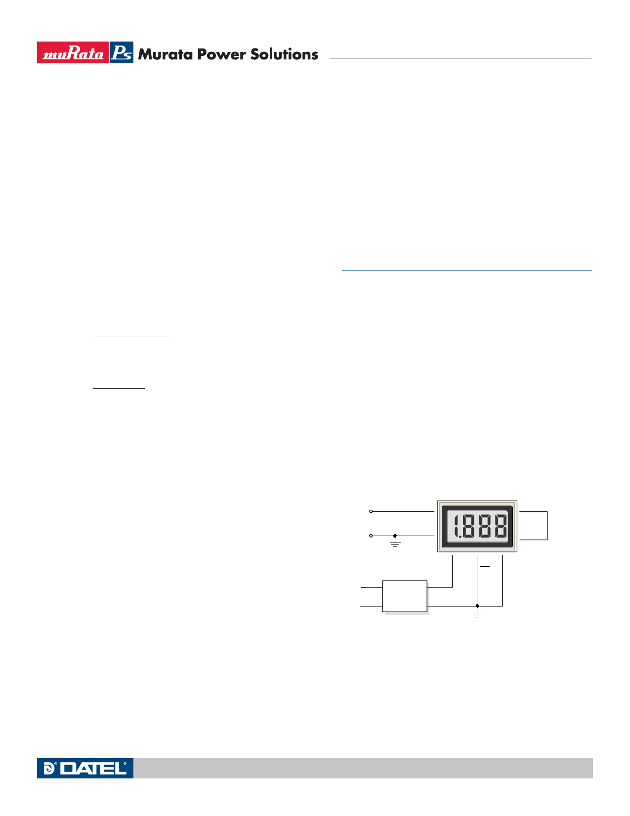
1. Single-Ended Input Conп¬Ғgurations: True single-ended measure-
ments can only be made with 5V-powered meters. The circuit of Figure
2 avoids problems normally associated with ground-loop currents.
Separate ground runs should be used for 5V RETURN (pin 3) and (вҖ“)
INPUT LO (pin 12).
11
DMS-20LCD-1-5
8
(+) IN HI
+
REF OUT
VIN
вҖ“
12
(вҖ“) IN LO
1
+5V SUP
7
REF IN
6
3
DP1
5V RET
120 VAC
DATEL
UPA-5/500
AC to DC Converter
Figure 2. Single-Ended Input Conп¬Ғguration
(5V-Powered Models)
www.murata-ps.com
Technical enquiries email: sales@murata-ps.com, tel: +1 508 339 3000
MPM_DMS20lcd.B03 Page 3 of 6
Share Link: 