DMS-20LCD жҹҘзңӢж•ёж“ҡиЎЁпјҲPDFпјү - Murata Power Solutions
йӣ¶д»¶зј–еҸ·
дә§е“ҒжҸҸиҝ° (еҠҹиғҪ)
з”ҹдә§еҺӮ家
DMS-20LCD Datasheet PDF : 6 Pages
| |||
APPLICATIONS
RShunt = R1 = VFsr / IFsr
Where: VFsr = Full scale reading (in Volts)
IFsr = Relative full scale current (in Amps)
Example: For a meter with a 2V full scale input (1.999 full
scale reading) and a desired full scale display reading of
1000 (with an input of 20mA), VFsr = 1.000 Volts
RShunt = 1.000V/(0.020 вҖ“ 0.004)A
RShunt = 1.000V/0.016A = 62.5 Ohms
To calibrate the circuit of Figure 7, perform the following:
1. With 4mA applied, adjust the 50k7 potentiometer (R2) to
display a reading of "000" (assuming that is the desired
reading).
2. With 20mA applied, adjust the gain-adjust potentiometer on
the back of the meter to display a reading of "1999". For different full
scale readings, alter the value of RShunt accordingly.
4-20mA R1
вҖ“
11
(+) IN HI
10
ANA COMM
DMS-20LCD-1-5
8
REF OUT
12
(вҖ“) IN LO
1
R2
+5V SUP
50k
7
REF IN
3
5V RET
120 VAC
DATEL
UPA-5/500
AC to DC Converter
Figure 7. 4-to-20mA Current Loop Operation
(5V-Powered Models)
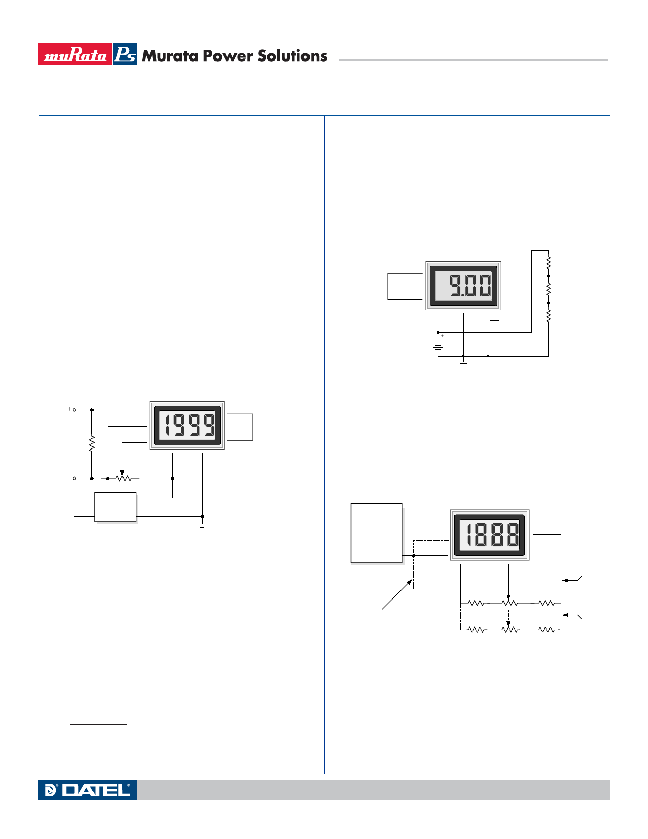
6. Power Supply Monitoring: A popular application for DATELвҖҷs low-
power LCD meters is monitoring the supply voltage in battery-oper-
ated portable equipment. Figure 8 demonstrates how a 9V-powered
DMS-20LCD can be used to monitor its own supply. The meter used
is the DMS-20LCD-1-9. A three-resistor voltage divider is used to
attenuate the battery voltage and also to satisfy the requirement that
the input voltages applied to pins 12 and 11 be at least 1.5 Volts above
and below the battery voltage applied to pins 1 (+BATTERY) and 3
(вҖ“BATTERY). The divider should be designed so that 1/10th the bat-
tery voltage falls across the inputs to the meter:
R2
= 0.1
(R1 + R2 + R3)
DMS-20LCD Series
3ВҪ Digit, LCD Display Digital Panel Voltmeters
Therefore, the 9V battery voltage appears to the meter inputs as 0.9V.
With the decimal point moved to its DP2 position
(pin 5 tied to pin 3), the meter reads 9.00 Volts.
The circuit can be calibrated by п¬Ғrst measuring the actual battery volt-
age with another meter and then adjusting the gain-adjust potentiom-
eter on the back of the DMS-20LCD until a similar reading is obtained.
If possible, the resistors in the divider should be Вұ1% metal-п¬Ғlm types
with TCRвҖҷs less than 50ppm/В°C.
REF OUT 8
DMS-20LCD-1-9
11
(+) IN HI
REF IN 7
1
+BAT
9V
BATTERY
вҖ“
12
(вҖ“) IN LO
3
5
вҖ“BAT DP2
R1
45.3k
R2
10.1k
R3
45.3k
Figure 8. Power Supply Monitor
(9V-Powered Models)
7. External Gain Adjustment: Connect REFERENCE OUT
(pin 8) to REFERENCE IN (pin 7) for normal, factory calibrated,
operation. Use the circuit shown in Figure 9 for applications needing
external gain adjustment. Calibration is performed with a precise,
near-full-scale, input voltage.
OUT
VOLTAGE
12 CALIBRATOR
COM
11
(+) IN HI
DMS-20LCD
3
5V RET/
вҖ“BAT IN
12
(вҖ“) IN LO
10
ANA
COMM
8
7
NC REF
IN
8.06k, 1%
2k
1
+5V IN/
+BAT IN
Connections
for Вұ2V, Вұ20V
and Вұ200V models
17.4k, 1%
For +5V models, tie (вҖ“) IN LO to pin 3.
For +9V models, tie (вҖ“) IN LO to pin 10
732, 1%
200
24.3k, 1%
= 10 to 20 Turns
Connections
for Вұ200mV
models
Figure 9. External Gain Adjustment
www.murata-ps.com
Technical enquiries email: sales@murata-ps.com, tel: +1 508 339 3000
MPM_DMS20lcd.B03 Page 5 of 6
Share Link: 