MAX798 查看數據表(PDF) - Maxim Integrated
零件编号
产品描述 (功能)
生产厂家
MAX798 Datasheet PDF : 12 Pages
| |||
High-Accuracy Step-Down Controller
with Synchronous Rectifier for CPU Power
______________________________________________________________Pin Description
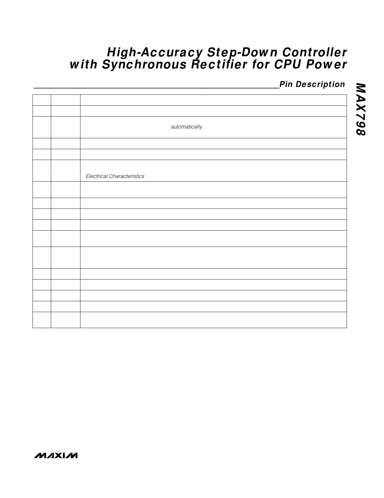
PIN NAME
FUNCTION
1
SS
Soft-Start Timing Capacitor Connection. Ramp time to full current limit is approximately 1ms/nF.
Disables pulse-skipping mode when high. Connect to GND for normal use. Don’t leave SKIP unconnected.
2
SKIP
With SKIP grounded, the device will automatically change from pulse-skipping operation to full PWM opera-
tion when the load current exceeds approximately 30% of maximum.
3
REF
Reference Voltage Output. Bypass to GND with 0.33µF minimum.
4
GND
Low-Noise Analog Ground and Feedback Reference Point
Oscillator Synchronization and Frequency Select. Tie to GND or VL for 150kHz operation; tie to REF for
5
SYNC 300kHz operation. A high-to-low transition begins a new cycle. Drive SYNC with 0V to 5V logic levels (see the
Electrical Characteristics table for VIH and VIL specifications). SYNC capture range is 195kHz to 340kHz.
6
SHDN
Shutdown Control Input, active low. Logic threshold is set at approximately 1V (VTH of an internal N-channel
MOSFET). Tie SHDN to V+ for automatic start-up.
7
FB
Feedback Input. Regulates at FB = 1.6V. Connect FB to a resistor divider to set the output voltage.
8
CSH
Current-Sense Input, high side. Current-limit level is 100mV referred to CSL.
9
CSL
Current-Sense Input, low side
10
V+
Battery Voltage Input (4.5V to 30V). Bypass V+ to PGND close to the IC with a 0.1µF capacitor. Connects to a
linear regulator that powers VL.
5V Internal Linear-Regulator Output. VL is also the supply voltage rail for the chip. VL is switched to the out-
11
VL
put voltage via CSL (VCSL > 4.5V) for automatic bootstrapping. Bypass to GND with 4.7µF. VL can supply
up to 5mA for external loads.
12 PGND Power Ground
13
DL
Low-Side Gate-Drive Output. Normally drives the synchronous-rectifier MOSFET. Swings 0V to VL.
14
BST
Boost Capacitor Connection for high-side gate drive (0.1µF)
15
LX
Switching Node (inductor) Connection. Can swing 2V below ground without hazard.
16
DH
High-Side Gate-Drive Output. Normally drives the main buck switch. DH is a floating driver output that swings
from LX to BST, riding on the LX switching-node voltage.
_______________________________________________________________________________________ 5
Share Link: 