MAX798 查看數據表(PDF) - Maxim Integrated
零件编号
产品描述 (功能)
生产厂家
MAX798 Datasheet PDF : 12 Pages
| |||
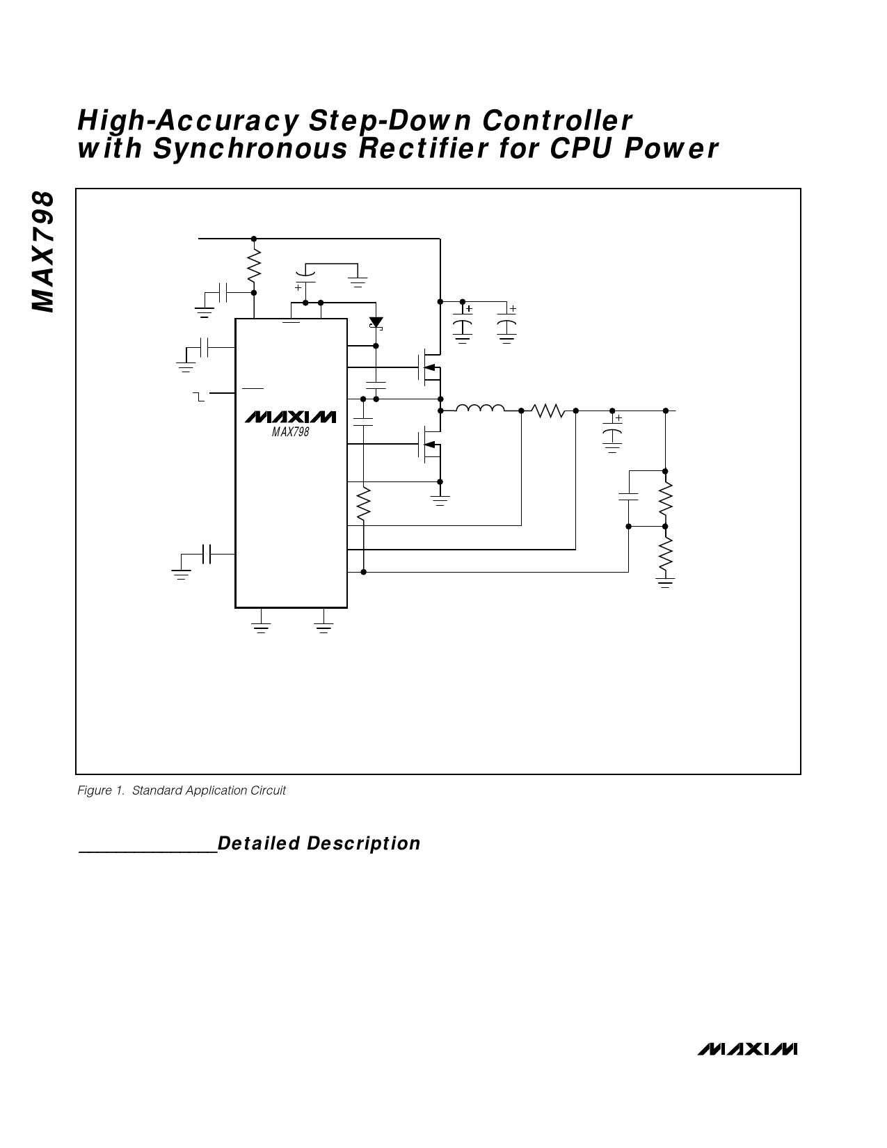
High-Accuracy Step-Down Controller
with Synchronous Rectifier for CPU Power
VIN, 4.5V TO 30V
R3
2.2µF
10Ω
4.7µF
0.33µF
ON
OFF
V+
REF
SHDN
SKIP VL
BST
DH
LX
MAX798
DL
0.1µF
C3
47pF
0.01µF
SS
SYNC
PGND
R4
1M
CSH
CSL
FB
GND
C1
C2
Q1
L1
12µH
Q2
15mΩ
VOUT, +2.5V @ 4.2A
C4
C5
470pF
R1
R2
Q1, Q2 = SILICONIX Si4410DY or IRF7413
C1, C2 = 10µF/30V SANYO OS-CON (30SA10)
C4 = 470µF/4V SPRAGUE 594D SERIES (594D477X0004R2T)
L1 = SUMIDA CDRH127 120
R1 = 6.49kΩ, 1%
R2 = 11.5kΩ, 1%
f = 150kHz
Figure 1. Standard Application Circuit
_______________Detailed Description
The MAX798 is a BiCMOS, switch-mode power-supply
controller designed primarily for buck-topology regula-
tors in battery-powered applications where high accu-
racy, high efficiency, and low quiescent supply current
are critical. The MAX798 also works well in other
topologies such as boost, inverting, and CUK due to
the flexibility of its floating high-speed gate driver.
Light-load efficiency is enhanced by automatic idle-
mode operation—a variable-frequency pulse-skipping
mode that reduces losses due to MOSFET gate charge.
The step-down power-switching circuit consists of two
N-channel MOSFETs, a rectifier, and an LC output filter.
The output voltage is the average of the AC voltage at
the switching node, which is adjusted and regulated by
changing the duty cycle of the MOSFET switches. The
gate-drive signal to the N -channel high-side MOSFET
must exceed the battery voltage and is provided by a
flying capacitor boost circuit that uses a 100nF capaci-
tor connected between BST and LX.
6 _______________________________________________________________________________________
Share Link: 