IDT7015S17JB(1996) 查看數據表(PDF) - Integrated Device Technology
零件编号
产品描述 (功能)
生产厂家
IDT7015S17JB Datasheet PDF : 20 Pages
| |||
IDT7015S/L
HIGH-SPEED 8K x 9 DUAL-PORT STATIC RAM
MILITARY AND COMMERCIAL TEMPERATURE RANGES
DC ELECTRICAL CHARACTERISTICS OVER THE
OPERATING TEMPERATURE AND SUPPLY VOLTAGE RANGE (VCC = 5.0V ± 10%)
7015S
7015L
Symbol
|ILI|
|ILO|
Parameter
Input Leakage Current(1)
Output Leakage Current
Test Conditions
VCC = 5.5V, VIN = 0V to VCC
CE = VIH, VOUT = 0V to VCC
Min.
—
—
Max.
10
10
Min.
—
—
Max.
5
5
VOL
Output Low Voltage
IOL = 4mA
—
0.4
—
0.4
VOH
Output High Voltage
NOTE:
1. At Vcc < 2.0V, Input leakages are undefined.
IOH = -4mA
2.4
—
2.4
—
Unit
µA
µA
V
V
2954 tbl 08
DC ELECTRICAL CHARACTERISTICS OVER THE
OPERATING TEMPERATURE AND SUPPLY VOLTAGE RANGE(1) (VCC = 5.0V ± 10%)
Symbol
Parameter
ICC Dynamic Operating
Current
(Both Ports Active)
ISB1 Standby Current
(Both Ports — TTL
Level Inputs)
ISB2 Standby Current
(One Port — TTL
Level Inputs)
ISB3 Full Standby Current
(Both Ports — All
Test
Condition
CE = VIL, Outputs Open
SEM = VIH
f = fMAX(3)
CER = CEL = VIH
SEMR = SEML = VIH
f = fMAX(3)
CE CE "A"=VIL and "B" = VIH(5)
Active Port Outputs Open
f = fMAX(3)
SEMR = SEML = VIH
Both Ports CEL and
CER > VCC - 0.2V
Version
MIL.
S
L
COM’L. S
L
MIL.
S
L
COM’L. S
L
MIL.
S
L
COM’L. S
L
MIL.
S
L
7015X12
Com'l. Only
Typ.(2) Max.
—
—
—
—
170 325
170 275
—
—
—
—
25
70
25
60
—
—
—
—
105 200
105 170
—
—
—
—
7015X15
Com'l. Only
Typ.(2) Max.
—
—
—
—
170 310
170 260
—
—
—
—
25
60
25
50
—
—
—
—
105 190
105 160
—
—
—
—
7015X17
Com'l. Only
Typ.(2) Max. Unit
— — mA
——
170 310
170 260
— — mA
——
25 60
25 50
— — mA
——
105 190
109 160
— — mA
——
CMOS Level Inputs) VIN > VCC - 0.2V or
COM’L. S 1.0
VIN < 0.2V, f = 0(4)
L 0.2
SEMR = SEML > VCC - 0.2V
15 1.0
5 0.2
15 1.0 15
5 0.2 5
ISB4 Full Standby Current CE"A"< 0.2V and
(One Port — All
CE"B" > VCC - 0.2V(5)
MIL.
S—
——
— — — mA
L—
——
— ——
CMOS Level Inputs) SEMR = SEML > VCC - 0.2V
VIN > VCC - 0.2V or
COM’L. S 100 180 100 170 100 170 mA
VIN < 0.2V
L 100 150 100 140 100 140
Active Port Outputs Open,
f = fMAX(3)
NOTES:
2954 tbl 09
1. "X" in part numbers indicates power rating (S or L).
2. VCC = 5V, TA = +25°C, and are not production tested. ICCDC = 120mA(typ.)
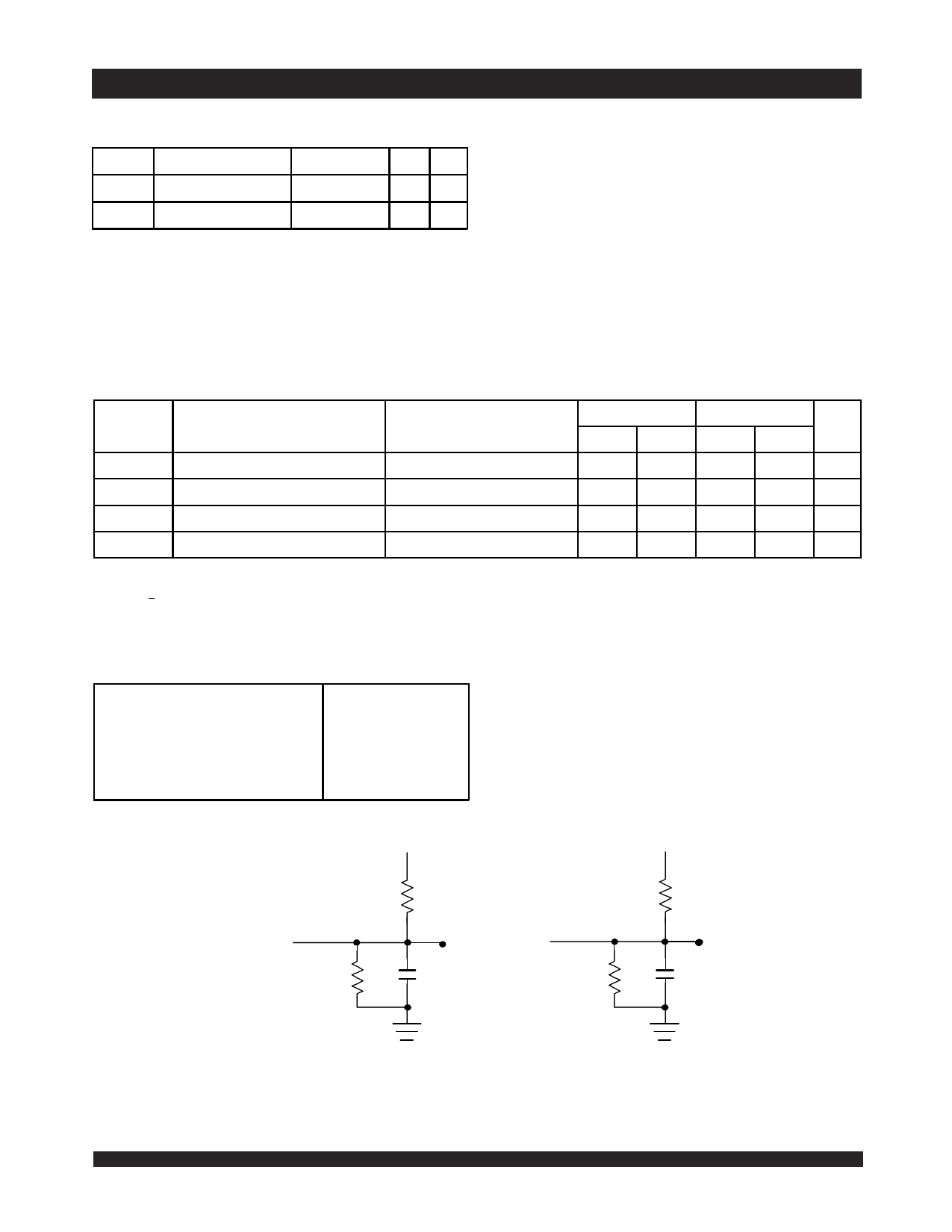
3. At f = fMAX, address and I/O'S are cycling at the maximum frequency read cycle of 1/tRC, and using “AC Test Conditions” of input levels of GND to 3V.
4. f = 0 means no address or control lines change.
5. Port "A" may be either left or right port. Port "B" is the opposite of port "A".
6.12
5
Share Link: 