LME0505DC 查看數據表(PDF) - Unspecified
零件编号
产品描述 (功能)
生产厂家
LME0505DC Datasheet PDF : 4 Pages
| |||
LME Series
Isolated 250mW Single Output DC-DC Converters
TEMPERATURE CHARACTERISTICS
Parameter
Conditions
Specification
All output types
Storage
Cooling
Free air convection
Min.
Typ.
Max.
Units
0
70
°C
-50
130
TEMPERATURE DERATING GRAPH
0.375
0.250
70°C
0.125
0
0
Safe Operating
Area
125°C
50
100
150
Ambient Temperature (°C)
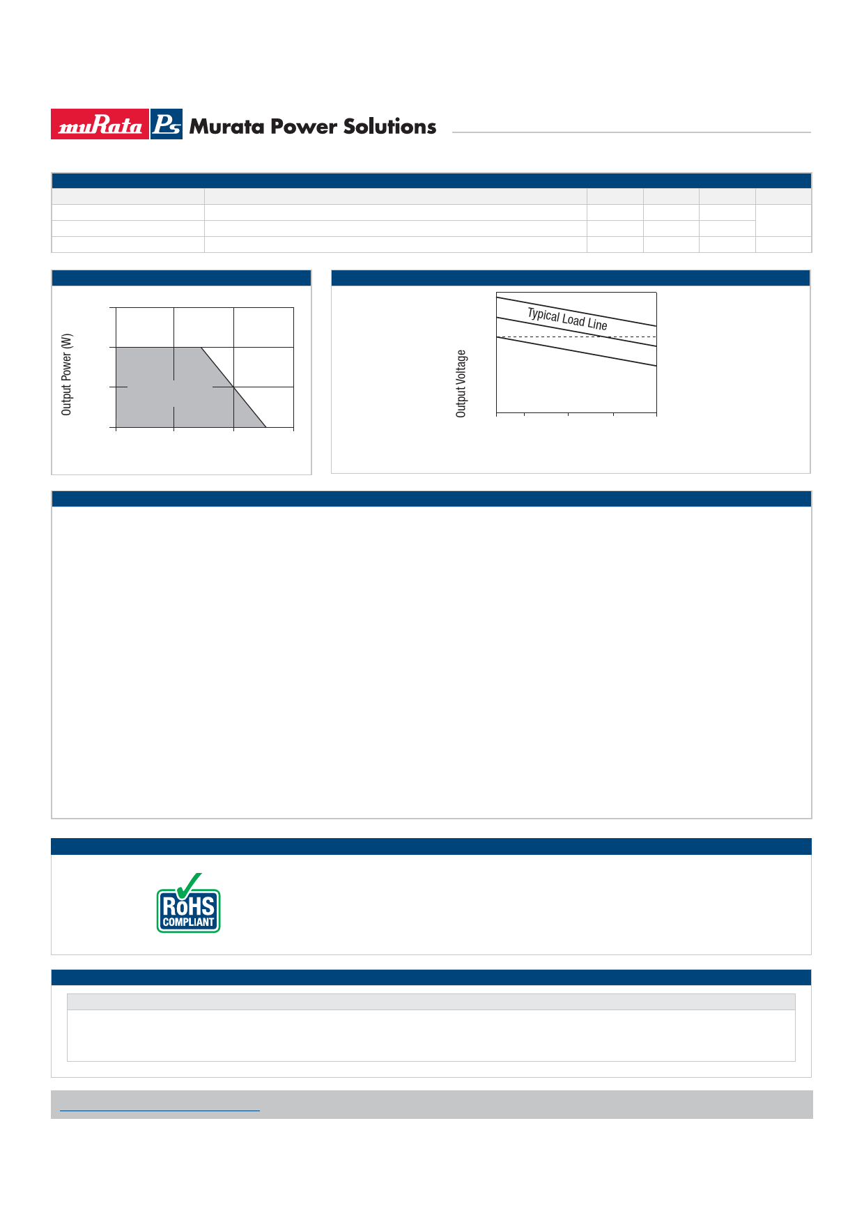
TOLERANCE ENVELOPE
+10%
+5%
V
NOM
Typical Load Line
+2.5%
-2.5%
-7.5%
10 25
50
75 100
Output Load Current (%)
The voltage tolerance envelope shows typical load regulation characteristics for this product series. The toler-
ance envelope is the maximum output voltage variation due to changes in output loading.
TECHNICAL NOTES
ISOLATION VOLTAGE
‘Hi Pot Test’, ‘Flash Tested’, ‘Withstand Voltage’, ‘Proof Voltage’, ‘Dielectric Withstand Voltage’ & ‘Isolation Test Voltage’ are all terms that relate to the same thing, a test voltage,
applied for a specified time, across a component designed to provide electrical isolation, to verify the integrity of that isolation.
Murata Power Solutions LME series of DC-DC converters are all 100% production tested at their stated isolation voltage. This is 1kVDC for 1 second.
A question commonly asked is, “What is the continuous voltage that can be applied across the part in normal operation?”
For a part holding no specific agency approvals, such as the LME series, both input and output should normally be maintained within SELV limits i.e. less than 42.4V peak, or
60VDC. The isolation test voltage represents a measure of immunity to transient voltages and the part should never be used as an element of a safety isolation system. The part
could be expected to function correctly with several hundred volts offset applied continuously across the isolation barrier; but then the circuitry on both sides of the barrier must
be regarded as operating at an unsafe voltage and further isolation/insulation systems must form a barrier between these circuits and any user-accessible circuitry according to
safety standard requirements.
REPEATED HIGH-VOLTAGE ISOLATION TESTING
It is well known that repeated high-voltage isolation testing of a barrier component can actually degrade isolation capability, to a lesser or greater degree depending on materials,
construction and environment. The LME series has toroidal isolation transformers, with no additional insulation between primary and secondary windings of enamelled wire. While
parts can be expected to withstand several times the stated test voltage, the isolation capability does depend on the wire insulation. Any material, including this enamel (typically
polyurethane) is susceptible to eventual chemical degradation when subject to very high applied voltages thus implying that the number of tests should be strictly limited. We
therefore strongly advise against repeated high voltage isolation testing, but if it is absolutely required, that the voltage be reduced by 20% from specified test voltage.
This consideration equally applies to agency recognised parts rated for better than functional isolation where the wire enamel insulation is always supplemented by a further
insulation system of physical spacing or barriers.
RoHS COMPLIANT INFORMATION
This series is compatible with RoHS soldering systems with a peak wave solder temperature of
260°C for 10 seconds. The pin termination finish on the SIP package type is Tin Plate, Hot Dipped
over Matte Tin with Nickel Preplate. The DIP types are Matte Tin over Nickel Preplate. Both types in
this series are backward compatible with Sn/Pb soldering systems.
For further information, please visit www.murata-ps.com/rohs
APPLICATION NOTES
Minimum Load
The minimum load to meet datasheet specification is 10% of the full rated load across the specified input voltage range. Lower than 10% minimum loading will result in an
increase in output voltage, which may rise to typically double the specified output voltage if the output load falls to less than 5%.
www.murata-ps.com/support
KDC_LMEC.G02 Page 2 of 4
Share Link: 