MAX3766EEP 查看數據表(PDF) - Maxim Integrated
零件编号
产品描述 (功能)
生产厂家
MAX3766EEP Datasheet PDF : 20 Pages
| |||
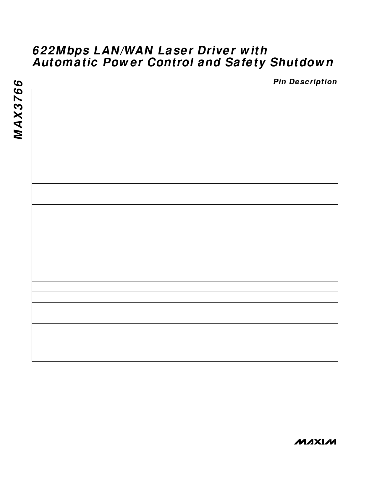
622Mbps LAN/WAN Laser Driver with
Automatic Power Control and Safety Shutdown
Pin Description
PIN
NAME
FUNCTION
1
BIASMAX
The current into BIASMAX sets the maximum laser bias current. Connecting BIASMAX directly to REF1
allows the largest possible bias current.
The resistance (RTC) between TC and REF1 programs the temperature coefficient of REF2. Connecting
2
TC
TC directly to REF1 produces the minimum tempco. Leaving TC unconnected produces the maximum
tempco.
3
REF2
REF2 is the reference voltage used to program the modulation current. The tempco of REF2 is pro-
grammed by RTC.
4
MOD
The current into MOD programs the laser modulation current. Connect MOD to REF2 with a resistor or
potentiometer.
5, 8
GND
Ground. All grounds must be connected.
6
IN-
Inverting Data Input
7
IN+
Noninverting Data Input
9
VCC
Positive Supply Voltage. All VCC pins must be connected.
10
ENABLE
ENABLE is a TTL-compatible input. When low or open, this pin disables the output modulation and bias
current.
A capacitor to ground at SAFETY determines the turn-on delay for the safety circuits. If SAFETY is
11
SAFETY
grounded or TTL low, internal safety shutdown features are disabled. A TTL high at SAFETY enables the
internal safety shutdown features.
12
FAIL
The FAIL output asserts low if the voltage at MD is above or below nominal. FAIL also asserts if REF1 is
inadvertently tied to the positive supply. FAIL has TTL-compatible output voltage levels.
13
VCCOUT
Supply Voltage for the Output Current Drivers
14
OUT-
Inverting Modulation-Current Output
15
OUT+
Noninverting Modulation-Current Output
16
BIAS
Connection for the DC Laser Bias Current
17
GNDOUT Ground for the Output Current Drivers
18
MD
Input for the laser monitor photodiode current.
19
POWERSET
The current into POWERSET programs the average optical output power when automatic power
control is used.
20
REF1
REF1 is a voltage reference used to program laser bias current and average power.
6 _______________________________________________________________________________________
Share Link: 