LF3310QC12 查看數據表(PDF) - LOGIC Devices
零件编号
产品描述 (功能)
生产厂家
LF3310QC12 Datasheet PDF : 21 Pages
| |||
DEVICES INCORPORATED
LF3310
Horizontal / Vertical Digital Image Filter
SIGNAL DEFINITIONS
Power
VCC and GND
+3.3 V power supply. All pins must
be connected.
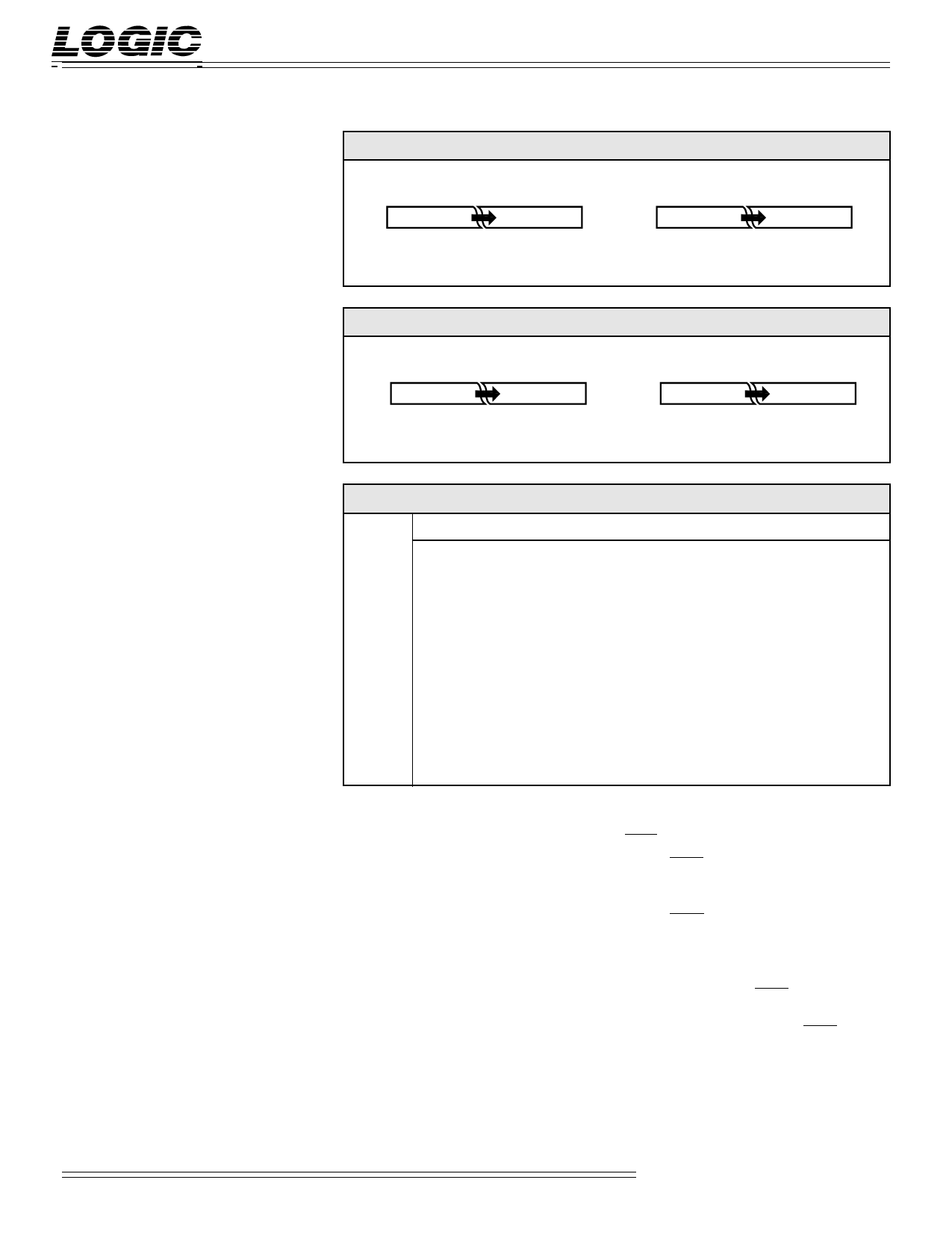
FIGURE 2. INPUT FORMATS
Input Data
11 10 9
–211 210 29
(Sign)
210
22 21 20
Coefficient Data
11 10 9
–20 2–1 2–2
(Sign)
210
2–9 2–10 2–11
Clock
CLK — Master Clock
The rising edge of CLK strobes all
enabled registers.
FIGURE 3. HORIZONTAL AND VERTICAL ACCUMULATOR FORMATS
Horizontal Accumulator Output
Vertical Accumulator Output
Inputs
DIN11-0 — Data Input
31 30 29
–220 219 218
(Sign)
210
2–9 2–10 2–11
31 30 29
–220 219 218
(Sign)
210
2–9 2–10 2–11
DIN11-0 is the 12-bit registered data
input port. Data is latched on the
rising edge of CLK.
HCF11-0 — Horizontal Coefficient Input
HCF11-0 is used to load data into the
horizontal coefficient banks and the
Configuration/Control Registers.
Data present on HCF11-0 is latched
into the Horizontal LF InterfaceTM on
the rising edge of CLK when HLD is
LOW (see the LF InterfaceTM section
for a full discussion).
HCA7-0 — Horizontal Coefficient
Address
TABLE 1. OUTPUT FORMATS
SLCT4-0 S11 S10 S9
···
00000 F11 F10 F9
···
00001 F12 F11 F10
···
00010 F13 F12 F11
···
·
···
·
···
·
···
10010 F29 F28 F27
···
10011 F30 F29 F28
···
10100 F31 F30 F29
···
S6 S5
F6 F5
F7 F6
F8 F7
··
··
··
F24 F23
F25 F24
F26 F25
···
···
···
···
···
···
···
S2 S1 S0
F2 F1 F0
F3 F2 F1
F4 F3 F2
···
···
···
F20 F19 F18
F21 F20 F19
F22 F21 F20
HCA7-0 determines which row of data
in the horizontal coefficient banks is
fed to the multipliers in the horizontal
filter. HCA7-0 is latched into the
Horizontal Coefficient Address
Register on the rising edge of CLK
when HCEN is LOW.
VCF11-0 — Vertical Coefficient Input
VCF11-0 is used to load data into the
vertical coefficient banks and the
Configuration/Control Registers.
Data present on VCF11-0 is latched
into the Vertical LF InterfaceTM on the
rising edge of CLK when VLD is
LOW (see the LF InterfaceTM section
for a full discussion).
VCA7-0 — Vertical Coefficient Address
VCA7-0 determines which row of data
in the vertical coefficient banks is fed
to the multipliers in the vertical filter.
VCA7-0 is latched into the Vertical
Coefficient Address Register on the
rising edge of CLK when VCEN is
LOW.
Outputs
DOUT11-0 — Data Output
DOUT11-0 is the 12-bit registered data
output port.
Controls
HLD — Horizontal Coefficient Load
When HLD is LOW, data on HCF11-0
is latched into the Horizontal LF
InterfaceTM on the rising edge of CLK.
When HLD is HIGH, data can not be
latched into the Horizontal LF
InterfaceTM. When enabling the LF
InterfaceTM for data input, a HIGH to
LOW transition of HLD is required in
order for the input circuitry to func-
tion properly. Therefore, HLD must
be set HIGH immediately after power
up to ensure proper operation of the
input circuitry (see the LF InterfaceTM
section for a full discussion).
Video Imaging Products
3
11/08/2001-LDS.3310-H
Share Link: 