TC7211AM 查看數據表(PDF) - TelCom Semiconductor, Inc
零件编号
产品描述 (功能)
生产厂家
TC7211AM Datasheet PDF : 7 Pages
| |||
BUS COMPATIBLE, 4-DIGIT
CMOS DECODER/DRIVER
TC7211AM
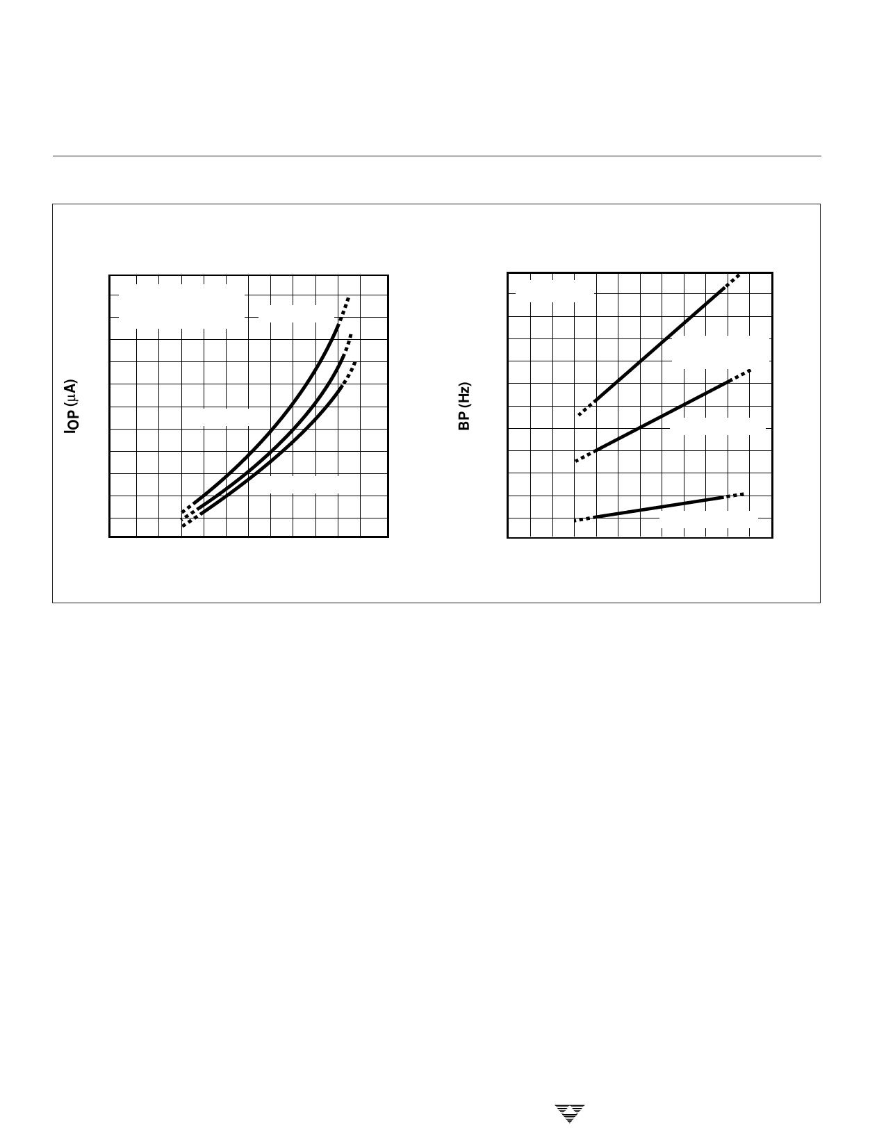
TYPICAL CHARACTERISTICS
Operating Supply Current
vs Supply Voltage
30
LCD DEVICES
25
DISPLAY BLANK
PIN 36 OPEN
TA= –20°C
20
15
TA= +25°C
10
5
TA= +70°C
0
1
2
3
4
5
6
7
V+ VOLTS
Backplane Frequency
vs Supply Voltage
180
TA = +25°C
150
COSC = 0 pF
120
(PIN 36 OPEN)
90
COSC = 22 pF
60
30
COSC = 220 pF
0
1
2
34
5
6
7
V+ VOLTS
BASIC OPERATION
The TC7211AM drives 4-digit, 7-segment LCDs. This
device contains 28 individual segment drivers, a backplane
driver, a self-contained oscillator, and a divider chain to
generate the backplane signal.
The 28 CMOS segment drivers and backplane driver
contain ratioed N- and P-channel transistors for identical ON
resistance. The equal resistances eliminate the DC output
driver component resulting from unequal rise and fall times.
This ensures maximum LCD life.
The backplane output driver can be disabled by ground-
ing the OSCILLATOR input (pin 36). The 28 output segment
drivers can therefore be synchronized directly to an input
signal at the backplane (BP) terminal (pin 5). Several slave
devices may be cascaded to the backplane output of a
master device. The backplane signal may also be derived
from an external source. These features permit interfacing to
single backplane LCDs with characters in multiples of four.
Each slave’s backplane input represents a 200pF
capacitive load to the master backplane driver (comparable
to one additional segment). The number of slave devices
drivable by a master device is therefore set by the larger
display backplane capacitive load. The master backplane
output will drive the display backplane of 16 one-half-inch
characters with rise and fall times under 5 µsec. This
represents a system with three slave devices and a fourth
master device driving the backplane.
6-12
If more than four devices are slaved together, the
backplane signal should be derived externally and all
TC7211AM devices slaved to it. The external drive signal
must drive a high capacitive load with 1µsec to 2 µsec rise
and fall times. The backplane frequency is normally 125
Hz. At lower display ambient temperatures, the frequency
may be reduced to compensate for display response time.
The on-chip RC oscillator free-runs at approximately
16 kHz. A divide-by 128 circuit provides the125 Hz backplane
frequency. The oscillator frequency may be reduced by
connecting an external capacitor between the oscillator
terminal and V+. (See typical operating characteristics
curves.)
The free-running oscillator may be overridden (if de-
sired) by an external clock. The backplane driver, however,
must not be disabled during the external clock’s negative or
lOW portion, as this will result in a DC drive component
being applied to the LCD, limiting the LCD’s life. To
prevent backplane driver disabling, the oscillator input
should be driven from the positive supply to no less than
one-fifth the supply voltage above ground. A backplane
disable signal will not be sensed if the driving signal remains
above ground by one-fifth the supply voltage. An alternate
method for externally driving the oscillator permits the
oscillator input to swing the full supply voltage range. The
oscillator input signal duty cycle is skewed so the LOW
TELCOM SEMICONDUCTOR, INC.
Share Link: 