U2400B 查看數據表(PDF) - Temic Semiconductors
零件编号
产品描述 (功能)
生产厂家
U2400B Datasheet PDF : 15 Pages
| |||
U2400B
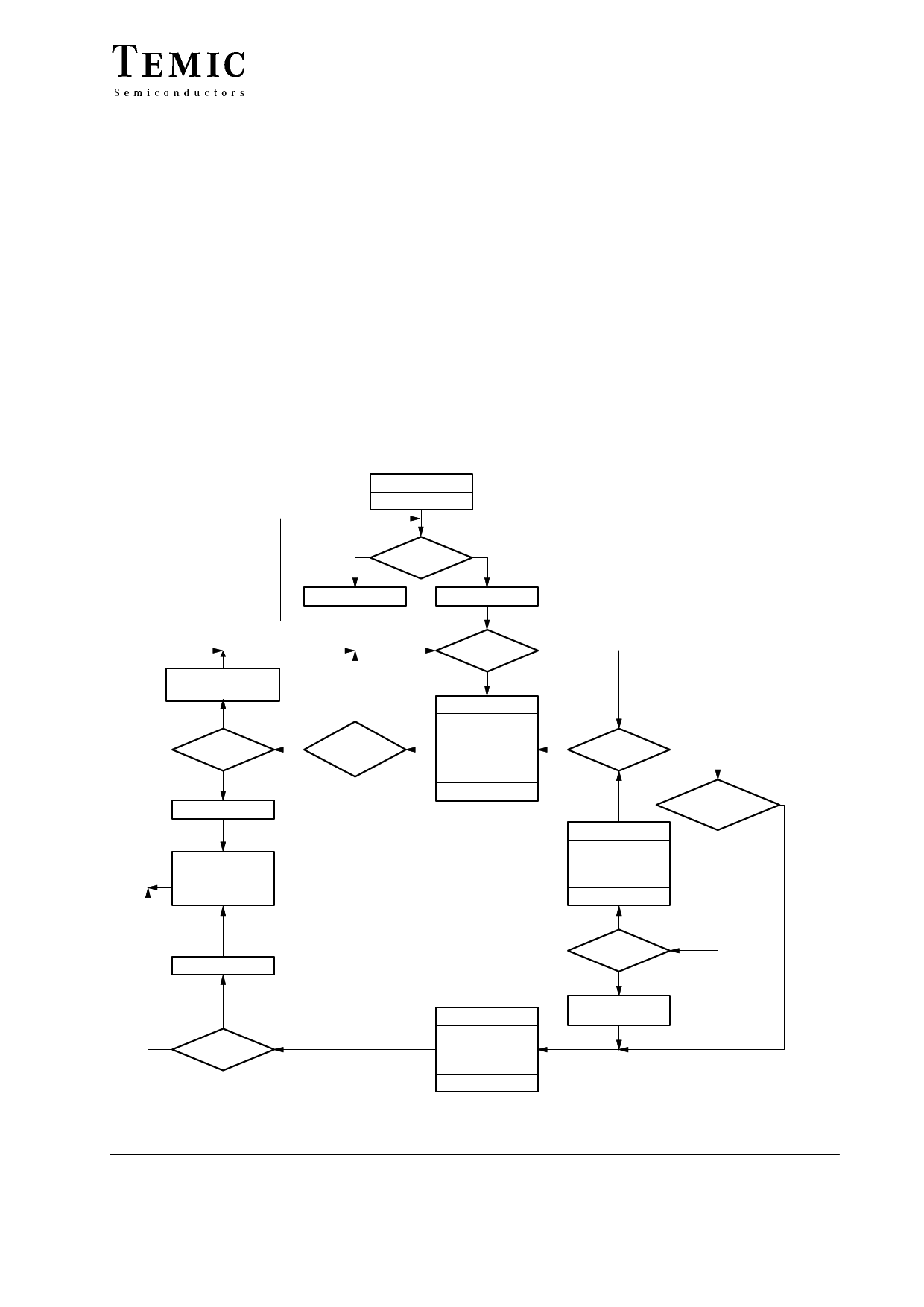
General Description, Figures 2 and 3
The integrated circuit, U2400B, supports specially the
controlled and defined charging of fast NiCd cells.
Varieties of charging time selections, i.e., standard charge
(12 h), quick charge (1 h) or fast charge (0.5 h) are
possible.
* * Before the charging begins, cell is discharged completely.
In this way, the long life Memory Effect of the
recharging cell remains intact. Surveillance is taken over
by control unit for time, thermal and voltage during the
charging and switch-off when the specified capacity is
attained. When switched on, the red LED connected to the
display output (Pin 9) is activated. This is only the case
if no battery is connected. When a battery is inserted with
a minimum voltage of approximately 180 mV at Pin 4,
the pre-discharge phase is then started with a 2 seconds
delay. The discharge output at Pin 10 is activated. This is
indicated by the flashing red LED (see figure 5). The
discharge procedure is stopped with a voltage less than
530 mV (at Pin 6). The following charge phase (charge
output Pin 12 active) is indicated by the flashing green
LED (Pin 9).
After the programmed charging period (Pin 13: 0.5 or 1 h
continuous charge, or 12 h pulsed charge) the trickle
charge phase is reached (figure 4). This trickle charge
mode is indicated by the on-state of the green LED. This
means, the battery has stored the maximum possible
* amount of energy. The outputs display, discharge and
* charge will be set inactive (by temperature, over-
voltage). The timer clock is interrupted during the
inactive phase and in each mode when a limit value
(Pins 4 and 5) is exceeded.
START
Reset
no
Pin 9: “0”
Battery
yes
inserted ?
Pin 9: “open”
Pin 9: Alternating
blinking
yes
Pin 15 = VRef
no
Pin 9: “0”
Trickle charge
Pin 12: “0” pulsed
Pin 10: open
Pin 9: “1”
yes
no
Time
t > tmax ?
yes
no Event counter
Z<2?
V < Vmax ?
no
STAND – BY
Increment
event counter
Pin 12: open
Pin 9: open
Pin 10: open
Timer stop
yes
no
yes
T < Tmax ?
Discharge
Pin12: open
Pin 9: “0” pulsed
Pin 10 “1”
Timer stop
no
yes
“Discharged”
memory set ?
no
Charge
Pin 12: “1” pulsed
Pin 9: “1” pulsed
Pin 10: open
Timer run
Figure 3. Flow chart
V < Vmin ?
yes
Set “discharged”
memory
94 9377
TELEFUNKEN Semiconductors
Rev. A2, 21-Nov-96
3 (15)
Share Link: 