NTE7134 查看數據表(PDF) - NTE Electronics
零件编号
产品描述 (功能)
生产厂家
NTE7134 Datasheet PDF : 17 Pages
| |||
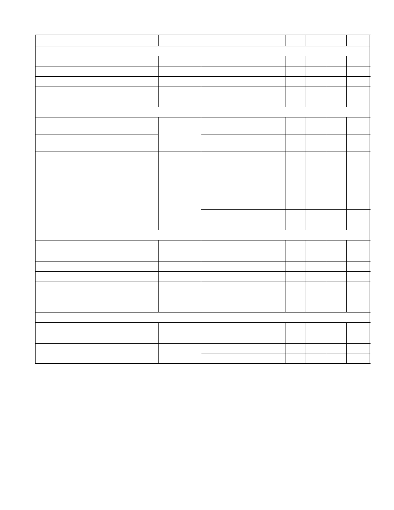
Electrical Characteristics (Cont’d): (VP = 12V, TA = +25°C unless otherwise specified)
Parameter
Symbol
Test Conditions
Min Typ Max
Video Clamping/Vertical Blanking Output (Cont’d) [CLCB (Pin16)]
Temperature Coefficient of Vblank(CLBL)
TCblank
Output Voltage During Vertical Scan
Vscan(CLBL) ICLBL = 0
Temperature Coefficient of Vscan(CLBL)
TCscan
Internal Sink Current
Isink(CLBL)
External Load Current
Iload(CLBL)
Selection of Leading/Trailing Edge for Video Clamping Pulse
– +2 –
0.59 0.63 0.67
– –2 –
2.4 –
–
–
– –3.0
Voltage at CLSEL (Pin10) for Trigger with
Leading Edge of Horizontal Sync
VCLSEL
7
– VCC
Voltage at CLSEL (Pin10) for Trigger with
Trailing Edge of Horizontal Sync
0
–
5
Delay Between Leading Edge of
Horizontal Sync and Start of
Horizontal Clamping Pulse
td(clamp)
VCLSEL > 7V
– 300 –
Delay Between Leading Trailing of
Horizontal Sync and Start of
Horizontal Clamping Pulse
VCLSEL < 5V
– 130 –
Maximum Duration of Video Clamping
Pulse After End of Horizontal Sync
tclamp(max)
VCLBL = 3V, VCLSEL > 7V
VCLBL = 3V, VCLSEL > 5V
–
– 0.15
–
– 1.0
Input Resistance at CLSEL (Pin10)
RCLSEL
VCLSEL ≤ VCC
80 –
–
PLL1 Phase Comparator and Frequency–Locked Loop [HPLL1 (Pin26) and HBUF (Pin27)]
Maximum Width of Horizontal Sync Pulse
(Referenced to Line Period)
Total Lock–In Time of PLL1
Control Voltage
Buffered f/v Voltage at HBUF (Pin27)
Maximum Load Current
Adjustment of Horizontal Picture Position
tHSYNC(max)
tlock(HPLL1)
VHPLL1
VHBUF
Iload(HBUF)
fH < 45kHz, Note 2
fH > 45kHz, Note 3
Note 4, Note 5
fH(min), Note 6
fH(max), Note 6
–
– 20
–
– 25
– 40 80
– 5.6 –
– 2.5 –
–
– –4.0
Horizontal Shift Adjustment Range
(Referenced to Horizontal Period)
Input Current
∆HPOS
IHPOS
IHSHIFT = 0
IHSHIFT = –135µA
∆HPOS = +10.5%
∆HPOS = –10.5%
– –10.5 –
– +10.5 –
–110 –120 –135
–
0
–
Unit
mV/K
V
mV/K
mA
mA
V
V
ns
ns
µs
µs
kΩ
&
%
ms
V
V
mA
%
%
µA
µA
Note 3. To ensure safe locking of the horizontal oscillator, one of the following procedures is required:
a) Search mode starts always from fmin. Then the PLL1 filter components are a 3.3nF
capacitor from Pin26 to GND in parallel with an 8.2kΩ resistor in series with a 47nF
capacitor.
b) Search mode starts either from fmin or fmax with HPOS in middle position (IHPOS = 60µA).
Then the PLL1 filter components are a 1.5nF capacitor from Pin26 to GND in parallel
with a 27kΩ resistor in series with a 47nF capacitor.
c) After locking is achieved, HPOS can be operated in the normal way
Note 4. Loading of HPLL1 (Pin26) is not allowed.
Note 5. Oscillator frequency is fmin when no sync signal is present (no continuous blanking at Pin16).
Note 6. Voltage at HPPL1 (Pin26) is fed to HBUF (Pin27) via a buffer. Disturbances caused by hori-
zontal sync are removed by an internal sample–and–hold circuit.
Share Link: 