WSL2010R5000FBA жҹҘзңӢж•ёж“ҡиЎЁпјҲPDFпјү - Vishay Semiconductors
йӣ¶д»¶зј–еҸ·
дә§е“ҒжҸҸиҝ° (еҠҹиғҪ)
з”ҹдә§еҺӮ家
WSL2010R5000FBA
Vishay Semiconductors

WSL2010R5000FBA Datasheet PDF : 5 Pages
| |||
www.vishay.com
WSL
Vishay Dale
TECHNICAL SPECIFICATIONS
PARAMETER
UNIT
WSL RESISTOR CHARACTERISTICS
Component temperature coefficient
(including terminal) (1)
Element TCR (2)
Operating temperature range
Maximum working voltage (3)
ppm/В°C
ppm/В°C
В°C
V
Вұ 75 for 7 mО© to 0.5 О©
Вұ 110 for 5 mО© to 6.9 mО©
Вұ 150 for 3 mО© to 4.9 mО©
Вұ 275 for 1 mО© to 2.9 mО©
Вұ 400 for 0.5 mО© to 0.99 mО©
< 20
-65 to +170
(P x R)1/2
Notes
(1) Component TCR - total TCR that includes the TCR effects of the resistor element and the copper terminal
(2) Element TCR - only applies to the alloy used for the resistor element; refer to item 1 in the construction illustration on the following page
(3) Maximum working voltage - the WSL is not voltage sensitive, but is limited by power / energy dissipation and is also not ESD sensitive
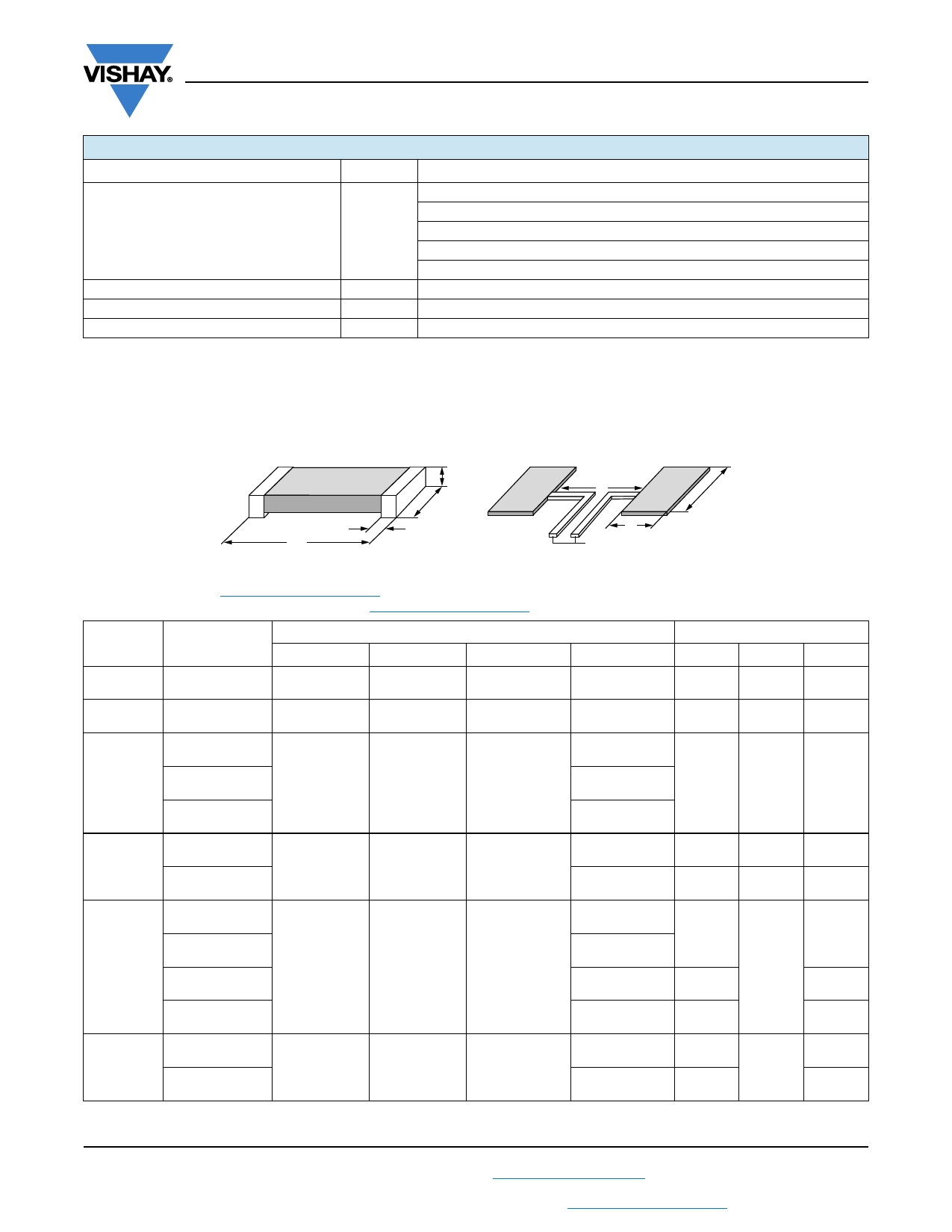
DIMENSIONS in inches (millimeters)
H
W
T
L
l
b
a
Typical sensing traces
Notes
вҖў 3D models available: www.vishay.com/doc?30306
вҖў Surface mount solder profile recommendations: www.vishay.com/doc?31052
MODEL
WSL0603
WSL0805
RESISTANCE
RANGE (О©)
0.01 to 0.1
0.005 to 0.2
L
0.060 Вұ 0.010
(1.52 Вұ 0.254)
0.080 Вұ 0.010
(2.03 Вұ 0.254)
DIMENSIONS
W
H
0.030 Вұ 0.010
(0.76 Вұ 0.254)
0.050 Вұ 0.010
(1.27 Вұ 0.254)
0.013 Вұ 0.005
(0.330 Вұ 0.127)
0.013 Вұ 0.005
(0.330 Вұ 0.127)
0.001 to 0.0019
WSL1206
0.002 to 0.0059
0.126 Вұ 0.010
(3.20 Вұ 0.254)
0.063 Вұ 0.010
(1.60 Вұ 0.254)
0.025 Вұ 0.010
(0.635 Вұ 0.254)
0.006 to 0.20
WSL2010
0.001 to 0.0069
0.007 to 0.5
0.200 Вұ 0.010
(5.08 Вұ 0.254)
0.100 Вұ 0.010
(2.54 Вұ 0.254)
0.025 Вұ 0.010
(0.635 Вұ 0.254)
0.0005 to 0.00099
WSL2512
0.001 to 0.0049
0.005 to 0.0069
0.250 Вұ 0.010
(6.35 Вұ 0.254)
0.125 Вұ 0.010
(3.18 Вұ 0.254)
0.025 Вұ 0.010
(0.635 Вұ 0.254)
0.007 to 0.5
WSL2816
0.002 to 0.00399
0.004 to 0.1
0.280 Вұ 0.010
(7.1 Вұ 0.254)
0.165 Вұ 0.010
(4.2 Вұ 0.254)
0.025 Вұ 0.010
(0.635 Вұ 0.254)
T
0.015 Вұ 0.010
(0.381 Вұ 0.254)
0.015 Вұ 0.010
(0.381 Вұ 0.254)
0.041 Вұ 0.010
(1.04 Вұ 0.254)
0.025 Вұ 0.010
(0.635 Вұ 0.254)
0.020 Вұ 0.010
(0.508 Вұ 0.254)
0.058 Вұ 0.010
(1.47 Вұ 0.254)
0.020 Вұ 0.010
(0.508 Вұ 0.254)
0.107 Вұ 0.010
(2.72 Вұ 0.254)
0.087 Вұ 0.010
(2.21 Вұ 0.254)
0.047 Вұ 0.010
(1.19 Вұ 0.254)
0.030 Вұ 0.010
(0.762 Вұ 0.254)
0.098 Вұ 0.010
(2.49 Вұ 0.254)
0.062 Вұ 0.010
(1.57 Вұ 0.254)
SOLDER PAD DIMENSIONS
a
b
l
0.040
(1.01)
0.040
(1.02)
0.040
(1.01)
0.050
(1.27)
0.020
(0.50)
0.020
(0.50)
0.062
(1.57)
0.070
(1.78)
0.030
(0.76)
0.093
(2.36)
0.055
(1.40)
0.120
(3.05)
0.083
(2.11)
0.065
(1.65)
0.135
(3.43)
0.096
(2.45)
0.120
(3.05)
0.120
(3.05)
0.145
(3.68)
0.185
(4.7)
0.055
(1.40)
0.130
(3.30)
0.050
(1.27)
0.125
(3.18)
0.160
(4.06)
0.060
(1.52)
0.125
(3.20)
Revision: 29-May-17
2
Document Number: 30100
For technical questions, contact: ww2bresistors@vishay.com
THIS DOCUMENT IS SUBJECT TO CHANGE WITHOUT NOTICE. THE PRODUCTS DESCRIBED HEREIN AND THIS DOCUMENT
ARE SUBJECT TO SPECIFIC DISCLAIMERS, SET FORTH AT www.vishay.com/doc?91000
Share Link: