MCRF200 查看數據表(PDF) - Microchip Technology
零件编号
产品描述 (功能)
生产厂家
MCRF200 Datasheet PDF : 24 Pages
| |||
MCRF200
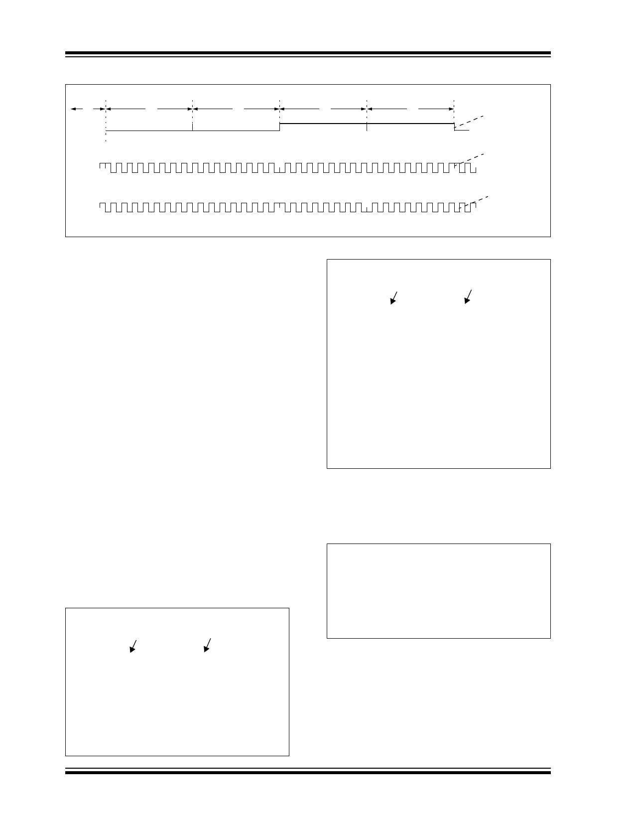
FIGURE 2-3:
PSK DATA MODULATION
‘1’
‘0’
‘0’
PP
PP
P
PP
P
2.2.4 MEMORY ARRAY LOCK BIT (CB12)
The CB12 must be ‘0’ for contactless programming
(Blank). The bit (CB12) is automatically set to ‘1’ as
soon as the device is programmed contactlessly.
2.3 Memory Section
The device has 128 bits of one-time programmable
(OTP) memory. The user can choose 96 or 128 bits by
selecting the CB1 bit in the configuration register. See
Table 2-4 for more details.
2.3.1
COLUMN AND ROW DECODER
LOGIC AND BIT COUNTER
The column and row decoders address the EEPROM
array at the clock rate and generate a serial data
stream for modulation. This data stream can be up to
128 bits in length. The size of the data stream is user
programmable with CB1 and can be set to 96 or 128
bits. Data lengths of 48 and 64 bits are available by
programming the data twice in the array, end-to-end.
The column and row decoders route the proper voltage
to the array for programming and reading. In the
programming modes, each individual bit is addressed
serially from bit 1 to bit 128.
2.4 Examples of Configuration
Settings
EXAMPLE 2-1: “08D” CONFIGURATION
The “08D” (hex) configuration is interpreted as
follows:
CB12
CB1
“08D” → 0000-1000-1101
Referring to Table 2-4, the “08D” configuration
represents:
Modulation = PSK_1
PSK rate = rf/2
Data encoding = NRZ_L (direct)
Baud rate = rf/32 = MOD32
Memory size 128 bits
‘1’
‘1’
Encoded Data
(NRZ_L)
PSK_ 1
PP
Change on Data
PSK _2
Change on ‘1’
PP
EXAMPLE 2-2: “00A” CONFIGURATION
The “00A” (hex) configuration is interpreted as
follows:
CB12
CB1
“00A” → 0000-0000-1010
The MSB corresponds to CB12 and the LSB
corresponds to CB1 of the configuration register.
Therefore, we have:
CB12=0
CB8=0
CB4=1
CB11=0
CB7=0
CB3=0
CB10=0
CB6=0
CB2=1
CB9=0
CB5=0
CB1=0
Referring to Table 2-4, the “00A” configuration
represents:
Not programmed device (blank), anticollision:
disabled, FSK protocol, NRZ_L (direct) encod-
ing, MOD50 (baud rate = rf/50), 96 bits.
EXAMPLE 2-3:
MCRF200
CONFIGURATION FOR
FDX-B ISO ANIMAL
STANDARD PROTOCOL
(ASP)
The FDX-B ISO Specification is:
Modulation = ASK
Data encoding = Differential biphase
Baud rate = rf/32 = 4 Kbits/sec for 128 kHz
Memory size = 128 bits
Referring to Table 2-4, the equivalent MCRF200
configuration is: “14D”.
DS21219H-page 6
2003 Microchip Technology Inc.
Share Link: 