QLS20ZG 查看數據表(PDF) - Power-One Inc.
零件编号
产品描述 (功能)
生产厂家
QLS20ZG Datasheet PDF : 8 Pages
| |||
QLS25 DC-DC Series Data Sheet
25A Quarter-Brick
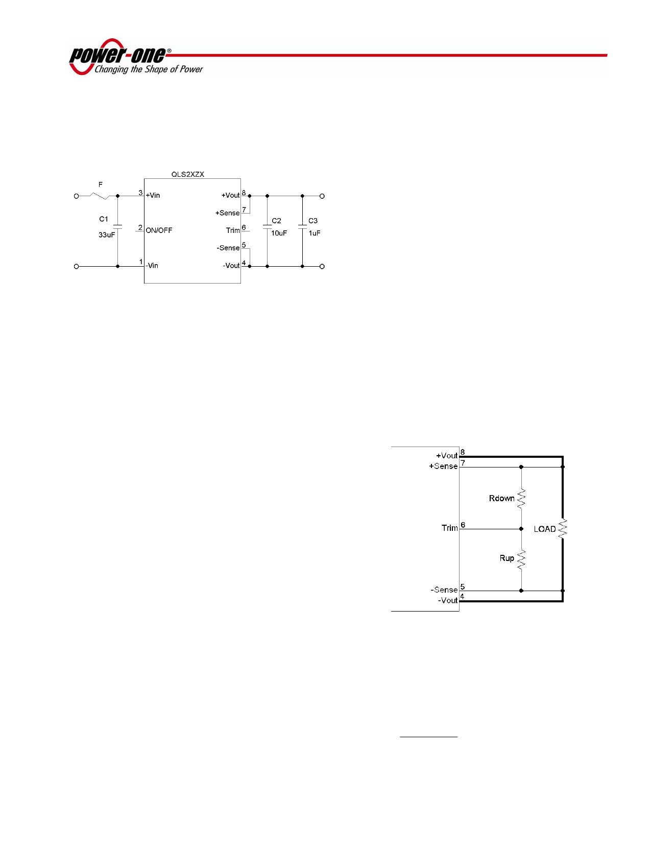
Typical Application
Figure 7 shows the recommended connections for
the QLS25 Series converter.
Figure 7. Typical application of QLS25 Series
The QLS25 Series converters do not require any
external components for proper operation. However,
if the distribution of the input voltage to the converter
contains significant inductance, the capacitor C1
may be required to enhance performance of the
converter. A minimum of a 33μF electrolytic
capacitor with the ESR<0.7Ω is recommended for
the QLS25 Series.
Refer to the “Inrush Current Control Application
Note” on www.power-one.com for suggestions on
how to limit the magnitude of the inrush current.
For output decoupling we recommend to use a 10μF
tantalum and a 1μF ceramic capacitors connected
directly across the output pins of the converter.
Note, that the capacitors do not substitute the
filtering required by the load.
When the ON/OFF pin is used to achieve remote
control, the user must take care to insure that the pin
reference for the control is really the -Vin pin. The
control signal must not be referenced ahead of EMI
filtering, or remotely from the unit. Optically coupling
the information and locating the optical coupler
directly at the module will solve any of these
problems.
Note:
If the ON/OFF pin is not used, it can be left floating (positive logic),
or connected to the -Vin pin (negative logic).
Output Voltage Trim
The trim feature allows the user to adjust the output
voltage from the nominal. This can be used to
accommodate a different requirement or to do
production margin testing. There are two variances
available in the QLS25 Series.
Negative Trim
The QLS25 negative trim units trim up with a resistor
from the TRIM pin to the –Sense pin and trim down
with a resistor from the TRIM pin to the +Sense pin
as shown in Figure 8.
The negative trim schematic is shown in Figure 8.
Shutdown Feature Description
The ON/OFF pin in the QLS25 Series converters
functions as a normal soft shutdown. It is referenced
to the –Vin pin (see Figure 7). With the positive
logic, when the ON/OFF pin is pulled low, the output
is turned off and the unit goes into a very low input
power mode.
With negative logic, when the ON/OFF pin is pulled
low, the unit is turned on.
An open collector switch is recommended to control
the voltage between the ON/OFF pin and the -Vin
pin of the converter. The ON/OFF pin is pulled up
internally, so no external voltage source is required.
The user should avoid connecting a resistor between
the ON/OFF pin and the +Vin pin.
Figure 8. QLS25 Series Negative Trim Schematic
The general equation (1) for changing the output
voltage on the negative trim modules is invariant, but
the constants in the equation change due to different
internal values.
RTRIM
=
A − B × ΔV
ΔV
,
kΩ
(1)
SEP 12, 2003 revised to OCT 26, 2006
Page 5 of 8
www.power-one.com
Share Link: 