UWR-12/665-D5A-C 查看數據表(PDF) - Unspecified
零件编号
产品描述 (功能)
生产厂家
UWR-12/665-D5A-C Datasheet PDF : 6 Pages
| |||
UWR Series
Single Output, High Reliability, 2" x 1", 6-10 Watt, DC-DC Converters
Input Fusing
Certain applications and/or safety agencies may require the installation of
fuses at the inputs of power conversion components. For Murata Power
Solutions A-Series UWR 6-10 Watt DC/DC Converters, you should use slow-
blow type fuses with values no greater than the following:
VIN Range
D5A
D12A and D24E
D48A and D48E
Fuse Value
3A
2A
1A
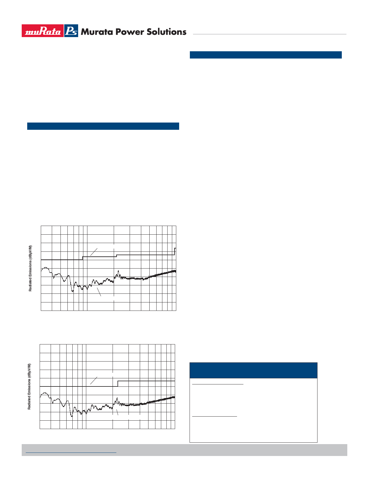
EMI RADIATED EMISSIONS
If you’re designing with EMC in mind, please note that all of Murata Power
Solutions' A-Series UWR 6-10 Watt DC/DC Converters have been character-
ized for radiated and conducted emissions in our new EMI/EMC labora-
tory. Testing is conducted in an EMCO 5305 GTEM test cell utilizing EMCO
automated EMC test software. Radiated emissions are tested to the limits
of FCC Part 15, Class B and CISPR 22 (EN 55022), Class B. Radiated emis-
sions plots to FCC and CISPR 22 for model UWR-12/665-D5A appear below.
UWR-12/665-D5A Radiated Emissions
FCC Part 15 Class B, 3 Meters
Converter Output = 12Vdc @ 620mA
80
70
60
FCC Class B Limit
50
40
30
20
10
0
Radiated Emissions
–10
–20
100
1000
Frequency (MHz)
UWR-12/665-D5A Radiated Emissions
EN 55022 Class B, 10 Meters
Converter Output = 12Vdc @ 620mA
80
70
60
50
EN 55022 Class B Limit
40
30
20
10
0
Radiated Emissions
–10
–20
100
Frequency (MHz)
1000
CUSTOM CAPABILITIES
Murata Power Solutions' world-class design, development and manu-
facturing team stands ready to work with you to deliver the exact power
converter you need for your demanding, large volume, OEM applications.
And ... we’ll do it on time and within budget!
Our experienced applications and design staffs; quick-turn prototype
capability; highly automated, SMT assembly facilities; and in-line SPC
quality-control techniques combine to give us the unique ability to design
and deliver any quantity of power converters to the highest standards of
quality and reliability.
We have compiled a large library of DC/DC designs that are currently used
in a variety of telecom, medical, computer, railway, aerospace and indus-
trial applications. We may already have the converter you need.
Contact us. Our goal is to provide you the highest-quality, most cost-
effective power converters available.
Quality and Reliability
The A-Series are the first DC/DC Converters to emerge from Murata Power
Solutions' new, company-wide approach to designing and manufacturing
the most reliable power converters available. The five-pronged program
draws our Quality Assurance function into all aspects of new-product
design, development, characterization, qualification and manufacturing.
Design for Reliability
Design for Reliability is woven throughout our multi-phased, new-product-
development process. Design-for-reliability practices are fully documented
and begin early in the new-product development cycle with the following
goals:
1. To work from an approved components/vendors list ensuring the use of
reliable components and the rigorous qualification of new components.
2. To design with safety margins by adhering to a strict set of derating
guidelines and performing theoretical worst-case analyses.
3. To locate potential design weaknesses early in the product-development
cycle by using extensive HALT (Highly Accelerated Life Testing).
4. To prove that early design improvements are effective by employing a
thorough FRACA (Failure Reporting Analysis and Corrective Action) System.
Soldering Guidelines
Murata Power Solutions recommends the specifications below when installing these
converters. These specifications vary depending on the solder type. Exceeding these
specifications may cause damage to the product. Be cautious when there is high atmo-
spheric humidity. We strongly recommend a mild pre-bake (100° C. for 30 minutes). Your
production environment may differ; therefore please thoroughly review these guidelines
with your process engineers.
Wave Solder Operations for through-hole mounted prod-
ucts (THMT)
For Sn/Ag/Cu based solders:
Maximum Preheat Temperature
115° C.
Maximum Pot Temperature
270° C.
Maximum Solder Dwell Time
7 seconds
For Sn/Pb based solders:
Maximum Preheat Temperature
105° C.
Maximum Pot Temperature
250° C.
Maximum Solder Dwell Time
6 seconds
www.murata-ps.com/support
MDC_UWR6-10W Series.E01 Page 5 of 6
Share Link: 