UWR-12/1250-D5A-C 查看數據表(PDF) - Unspecified
零件编号
产品描述 (功能)
生产厂家
UWR-12/1250-D5A-C Datasheet PDF : 6 Pages
| |||
UWR Series
Single Output, High Reliability, 2" x 2", 14-20 Watt, DC/DC Converters
Input Fusing
Certain applications and/or safety agencies may require the installation of
fuses at the inputs of power conversion components. For Murata Power
Solutions A-Series UWR 14-20 Watt DC/DC Converters, you should use
slow-blow type fuses
with values no greater than the following:
VIN Range
D5A
D12A
D48A/D48E
Fuse Value
6A
4A
2A
On/Off Control
The On/Off Control pin (pin 4) may be used for remote on/off operation. A
TTL logic high (+2 to +5 Volts, 250µA max.) applied to pin 4 disables the
converter. A TTL logic low (0 to +0.8 Volts, 70µA max.), or no connection,
enables the converter. Control voltages should be referenced to pin 2
(–Input). Applying a voltage to the Control pin when no input power is
applied to the converter can cause permanent damage to the converter.
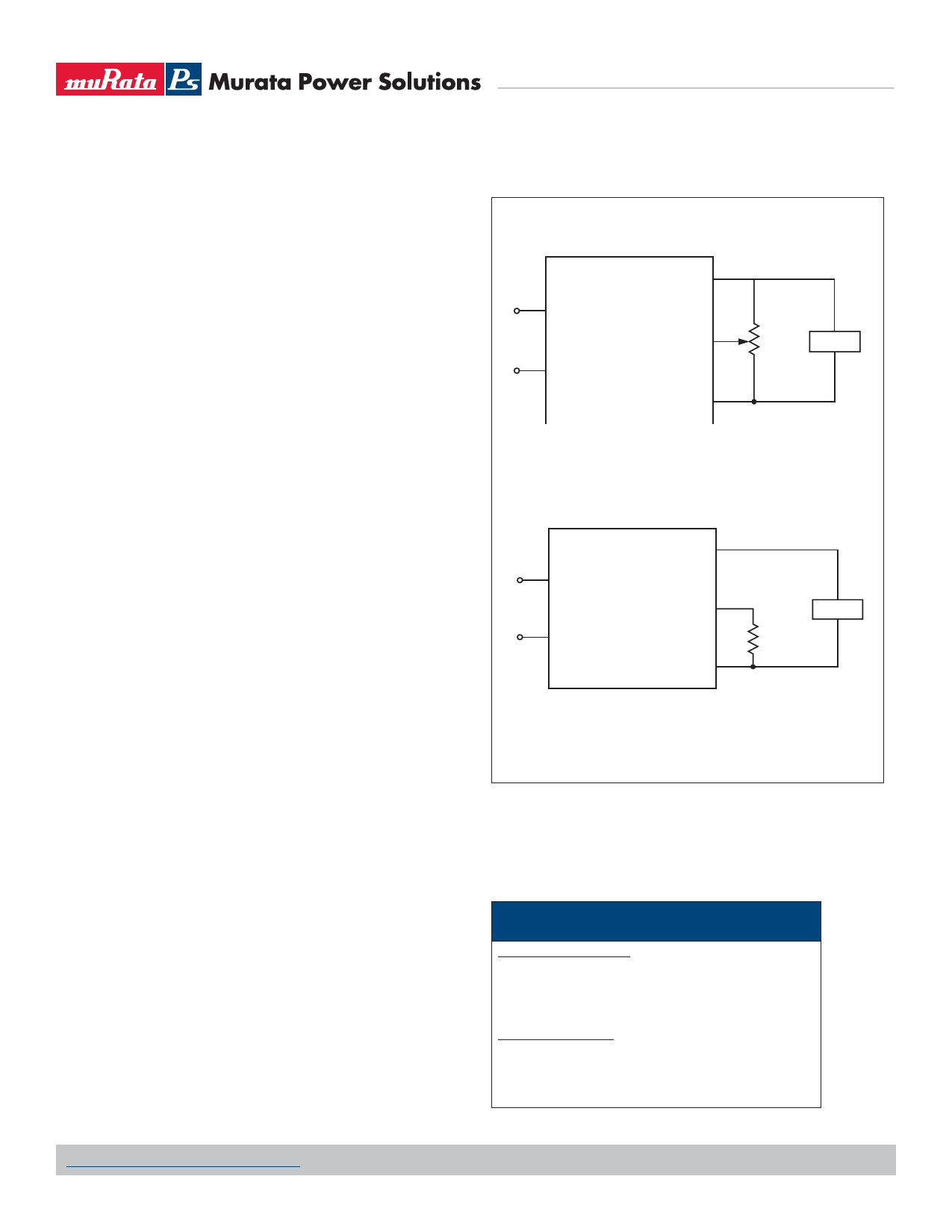
Output Trimming
VOUT may be trimmed up +5% only via a single external trimpot or fixed
resistor. The trimpot should be connected as shown in Figure 2a with its
wiper connected to pin 8 (Trim). A trimpot can be used to determine the
value of a single fixed resistor which should be connected as shown in
Figure 2b. Connect the resistor between pins 8 and 7 (Common) to trim
"up" the output voltage. Fixed resistors should be metal-film types with
absolute TCR’s less than 100ppm/°C to ensure stability.
Custom Capabilities
Murata Power Solutions' world-class design, development and manu-
facturing team stands ready to work with you to deliver the exact power
converter you need for your demanding, large volume, OEM applications.
More importantly . . . we’ll do it on time and within budget!
Our experienced applications and design staffs; quick-turn prototype
capability; highly automated, SMT assembly facilities; and in-line SPC
quality-control techniques combine to give us the unique ability to design
and deliver any quantity of power converters to the highest standards of
quality and reliability.
We have compiled a large library of DC/DC designs that are currently used
in a variety of telecom, medical, computer, railway, aerospace and industrial
applications. We may already have the converter you need.
Contact us. Our goal is to provide you the highest-quality, most cost-effec-
tive power converters available.
1 +VIN
2
–VIN
+VOUT 6
TRIM 8
20kΩ
5-10
TURNS
LOAD
7
COMMON
Figure 2a. Trim Connections Using a Trimpot
1 +VIN
2
–VIN
+VOUT 6
8
TRIM
COMMON 7
LOAD
Trim Up
Figure 2b. Trim Connections Using Fixed Resistors
Soldering Guidelines
Murata Power Solutions recommends the specifications below when installing these
converters. These specifications vary depending on the solder type. Exceeding these
specifications may cause damage to the product. Your production environment may dif-
fer; therefore please thoroughly review these guidelines with your process engineers.
Wave Solder Operations for through-hole mounted products
(THMT)
For Sn/Ag/Cu based solders:
Maximum Preheat Temperature
115° C.
Maximum Pot Temperature
270° C.
Maximum Solder Dwell Time
7 seconds
For Sn/Pb based solders:
Maximum Preheat Temperature
105° C.
Maximum Pot Temperature
250° C.
Maximum Solder Dwell Time
6 seconds
www.murata-ps.com/support
MDC_UWR14-20 Series.G01 Page 4 of 6
Share Link: 