1-1414310-0 查看數據表(PDF) - TE Connectivity
零件编号
产品描述 (功能)
生产厂家
1-1414310-0 Datasheet PDF : 4 Pages
| |||
n Limiting continuous current 45A
n Wide voltage range
n 24VDC coil versions available
Automotive Relays
PCB Single Relays
Power Relay K (Sealed)
Typical applications
ABS control, blower fans, car alarm, cooling fan, engine control, fuel pump,
hazard warning signal, heated front screen, heated rear screen, ignition,
lamps front/rear/fog light, interior lights, main switch/supply relay, seat
control, seatbelt pretensioner, sun roof, turn signal, valves, window lifter,
wiper control.
F076_fcw2b
Contact Data
Typical applications Resistive/inductive Resistive/inductive
Indicator lamps
Headlights,
Headlights
loads
loads
capacitive loads
capacitive loads
Contact arrangement 1 form A, 1 NO
1 form C, 1 CO
1 form A, 1 NO
1 form A, 1 NO
1 form C, 1 CO
Rated voltage 12VDC
12VDC
12VDC
12VDC
12VDC
A/B (NO/NC) A/B (NO/NC)
Rated current 45A
45/30A
30A
40A
40/25A
Limiting continuous current
23°C 45A
45/30A
30A
40A
40/25A
85°C 30A
30/25A
25A
25A
25/20A
Limiting making current1)
100A
100/30A
120A3)
180A
180/60A
Limiting breaking current2) 60A
60/30A
60A
60A
60/30A
Contact material
AgNi0.15
AgNi0.15
AgSnO2
Min. recommended contact load 1A at 5VDC4)
AgSnO2
AgSnO2
Initial voltage drop, at 10A, typ./max.
20/300mV
Operate/release time typ. 5/3ms5)
Electrical endurance >2x10⁵ ops.
>2x10⁵ ops.
>2.2x10⁶ ops.
>105 ops.
>105 ops.
at 13.5VDC, 40A
at 13.5VDC, 40A
up to 8x21W
up to 4x60W
up to 4x60W
Mechanical endurance, DC coil
>107 ops.
1) The values apply to a resistive or inductive load with suitable spark suppression and at maximum 13.5VDC for 12VDC or 27VDC for 24VDC load voltages.
2) For a load current duration of maximum 3s for a make/break ratio of 1:10.
3) Corresponds to a peak inrush current on initial actuation (cold filament).
4) See chapter Diagnostics of Relays in our Application Notes or consult the internet at http://relays.te.com/appnotes/
5) For unsuppressed relay coil. A low resistive suppression device in parallel to the relay coil increases the release time and reduces the lifetime caused by increased erosion and/or higher
risk of contact tack welding.
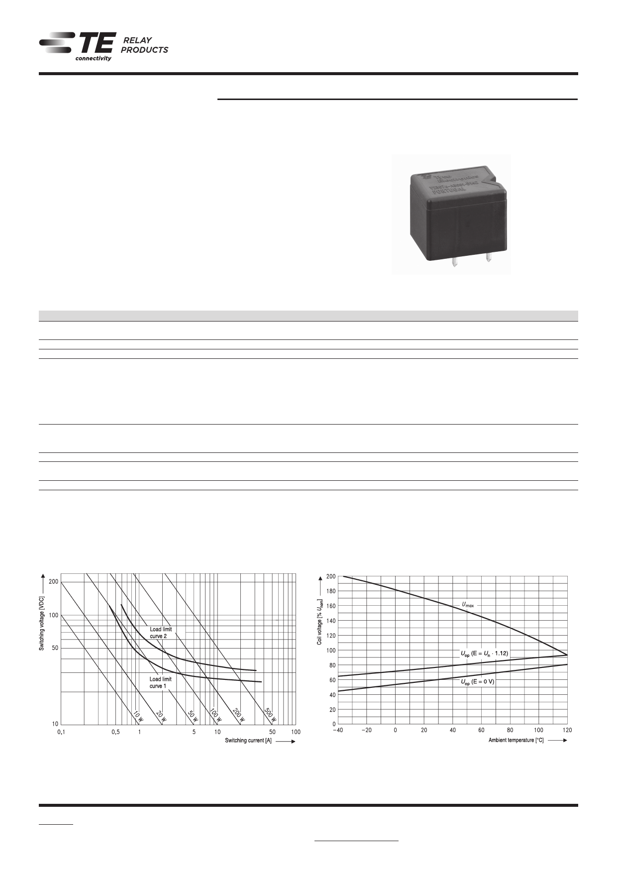
Max. DC load breaking capacity
TE0556-E
Coil operating range
TE0555-6
Does not tak
the temperat
the contact c
E = pre-ener
Load limit curve 1: arc extinguishes, during transit time (changeover contact).
Load limit curve 2: safe shutdown, no stationary arc (make contact).
Load limit curves measured with low inductive resistors verified for 1000 switching events.
Does not take into account the temperature rise due to the contact current
E = pre-energization
06-2014, Rev. 0614
www.te.com
© 2014 Tyco Electronics Corporation,
a TE Connectivity Ltd. company.
Catalog and product specification according
to IEC 61810-1 and to be used only together
with the ‘Definitions’ section.
Catalog and product data is subject to the
terms of the disclaimer and all chapters of
the ‘Definitions’ section, available at
http://relays.te.com/definitions
1
Catalog product data, ‘Definitions’ section,
application notes and all specifications are
subject to change.
Share Link: 