EB43-S1R2260X 查看數據表(PDF) - Vishay Semiconductors
零件编号
产品描述 (功能)
生产厂家
EB43-S1R2260X
Vishay Semiconductors

EB43-S1R2260X Datasheet PDF : 5 Pages
| |||
www.vishay.com
EB4
Vishay Dale
PHYSICAL SPECIFICATIONS
Contact Type: bifurcated cantilever beam
Number of Contacts: 10, 12, 15, 18, 20, 22, 25, 28, 30, 31,
35, 36, 40, 43, 44, 48, 49, 50, 60 and 65 per side
Contact Terminal Variation: Standard terminals
Type “C” - dip solder, 0.025" (0.635 mm) square terminals,
0.175" (4.44 mm) nominal terminal length below standoffs
Type “D” - dip solder, 0.025" (0.635 mm) square terminals,
0.115" (2.92 mm) nominal terminal length below standoffs
Type “K” - Wire Wrap™, 0.025" (0.635 mm) square
terminals, 0.570" (14.48 mm) nominal terminal length below
standoffs
Contact Terminal Variation: Right angle terminals
Type “1R” - dip solder, 0.025" (0.635 mm) square
terminals, 0.120" (3.05 mm) nominal terminal length x 0.150"
(3.81 mm) nominal terminal row spacing
Type “2R” - dip solder, 0.025" (0.635 mm) square
terminals, 0.120" (3.05 mm) nominal terminal length x 0.200"
(5.08 mm) nominal terminal row spacing
Type “3R” - dip solder, 0.025" (0.635 mm) square
terminals, 0.180" (4.57 mm) nominal terminal length x 0.150"
(3.81 mm) nominal terminal row spacing
Type “4R” - dip solder, 0.025" (0.635 mm) square
terminals, 0.180" (4.57 mm) nominal terminal length x 0.200"
(5.08 mm) nominal terminal row spacing
Contact Spacing: 0.100" (2.54 mm) center to center
Contact Terminal Row Spacing: Standard - 0.200"
(5.08 mm) nominal. Right angle - 0.200" (5.08 mm) nominal
and 0.150" (3.81 mm) nominal
Card Thickness: 0.054" to 0.071" (1.37 mm to 1.80 mm)
Card Slot Depth: 0.300" (7.62 mm)
Connector Polarization: between contact polarization
key(s) are located to the right of the contact position(s)
designated
Note
• High temperature burn-in, edgeboard connectors, with 0.100"
(2.54 mm) center to center are on www.vishay.com/doc?36006
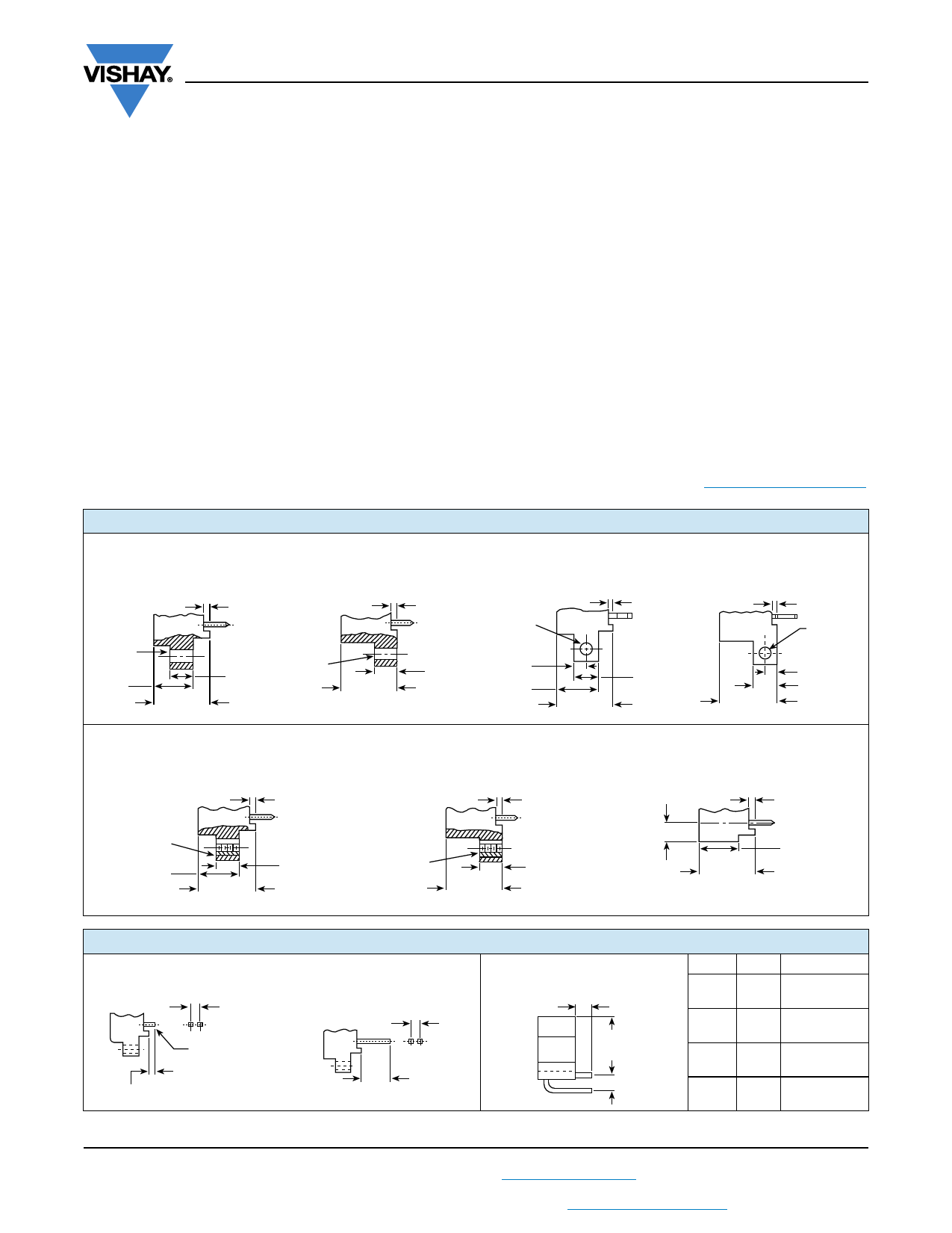
MOUNTING VARIATIONS in inches (millimeters)
Type “X”
Clearance Hole
Raised Mounting Flange
Type “XF”
Clearance Hole
Flush Mounting Flange
Type “XS”
Right Angle
Mounting Flange
Type “XFS”
Right Angle
Mounting Flange
0.060 (1.52) Ref.
0.125
(3.17)
Dia.
0.430
(10.92)
0.610
(15.49)
Ref.
0.250
(6.35)
0.060 (1.52) Ref.
0.125
(3.17)
Dia.
0.610
(15.49)
Ref.
0.250
(6.35)
0.125
(3.17)
Dia.
0.125
(3.17)
0.430
(10.92)
0.060 (1.52) Ref.
0.610
(15.49)
Ref.
0.250
(6.35)
0.060 (1.52) Ref.
0.125
(3.17)
Dia.
0.610
(15.49)
Ref.
0.125 (3.17)
0.250 (6.35)
Type “Y”
Threaded Insert
Raised Mounting Flange
Type “YF”
Threaded Insert
Flush Mounting Flange
Type “W”
No Mounting Flange
0.060 (1.52) Ref.
0.060 (1.52) Ref.
0.060 (1.52) Ref.
4-40
UNC-2B
0.430
(10.92)
0.610
(15.49)
Ref.
0.250
(6.35)
4-40
UNC-2B
0.610
(15.49)
Ref.
0.250
(6.35)
0.180 (4.57)
0.610
(15.49)
Ref.
0.430
(10.92)
TERMINAL VARIATIONS in inches (millimeters)
Type “C” and “D”
Solder Dip, Standard
0.025 (0.635) Square Terminals
0.200
(5.08)
To Fit
0.050 ± 0.002
(1.27 ± 0.051)
Dia. Eyelet
“C” = 0.175 (4.44)
“D” = 0.115 (2.92)
Type “K”
Wire Wrap™, Standard
0.025 (0.635) Square Terminals
0.200 (5.08)
0.570 (14.48)
Type “1R”, “2R”, “3R” and “4R”
Right Angle
0.025 (0.635) Square Terminals
B
0.590
(14.99)
A
TYPE
1R
2R
3R
4R
A
0.150
(3.81)
0.200
(5.08)
0.150
(3.81)
0.200
(5.08)
B
0.120 ± 0.030
(3.05 ± 0.762)
0.120 ± 0.030
(3.05 ± 0.762)
0.180 ± 0.030
(4.57 ± 0.762)
0.180 ± 0.030
(4.57 ± 0.762)
Revision: 16-Feb-09
3
Document Number: 36001
For technical questions, contact: connectors@vishay.com
THIS DOCUMENT IS SUBJECT TO CHANGE WITHOUT NOTICE. THE PRODUCTS DESCRIBED HEREIN AND THIS DOCUMENT
ARE SUBJECT TO SPECIFIC DISCLAIMERS, SET FORTH AT www.vishay.com/doc?91000
Share Link: