MKT1817368016G 查看數據表(PDF) - Vishay Semiconductors
零件编号
产品描述 (功能)
生产厂家
MKT1817368016G Datasheet PDF : 14 Pages
| |||
Not for New Designs - Alternative Device: MKT370
www.vishay.com
MKT1817
Vishay Roederstein
APPLICATION NOTE AND LIMITING CONDITIONS
These capacitors are not suitable for mains applications as across-the-line capacitors without additional protection, as
described hereunder. These mains applications are strictly regulated in safety standards and therefore electromagnetic
interference suppression capacitors conforming the standards must be used.
For capacitors connected in parallel, normally the proof voltage and possibly the rated voltage must be reduced. For information
depending of the capacitance value and the number of parallel connections contact: dc-film@vishay.com
To select the capacitor for a certain application, the following conditions must be checked:
1. The peak voltage (UP) shall not be greater than the rated DC voltage (URDC)
2. The peak-to-peak voltage (UP-P) shall not be greater than 22 x URAC to avoid the ionization inception level
3. The voltage peak slope (dU/dt) shall not exceed the rated voltage pulse slope in an RC-circuit at rated voltage and without
ringing. If the pulse voltage is lower than the rated DC voltage, the rated voltage pulse slope may be multiplied by URDC and
divided by the applied voltage.
For all other pulses following equation must be fulfilled:
T
2 x
d--d--U--t-
2
x
dt
URDC
x
d--d--U--t-
r
ated
0
T is the pulse duration.
4. The maximum component surface temperature rise must be lower than the limits (see graph “Max. allowed component
temperature rise”).
5. Since in circuits used at voltages over 280 V peak-to-peak the risk for an intrinsically active flammability after a capacitor
breakdown (short circuit) increases, it is recommended that the power to the component is limited to 100 times the values
mentioned in the table: “Heat Conductivity”
6. When using these capacitors as across-the-line capacitor in the input filter for mains applications or as series connected
with an impedance to the mains the applicant must guarantee that the following conditions are fulfilled in any case (spikes
and surge voltages from the mains included).
VOLTAGE CONDITIONS FOR 6 ABOVE
ALLOWED VOLTAGES
Maximum continuous RMS voltage
Maximum temperature RMS-overvoltage (< 24 h)
Maximum peak voltage (VO-P) (< 2 s)
Tamb 85 °C
URAC
1.25 x URAC
1.6 x URDC
85 °C < Tamb 100 °C FOR 63 V
85 °C < Tamb 100 °C FOR > 63 V
See “Max. AC voltage as function
of temperature” per characteristics
URAC
1.3 x URDC
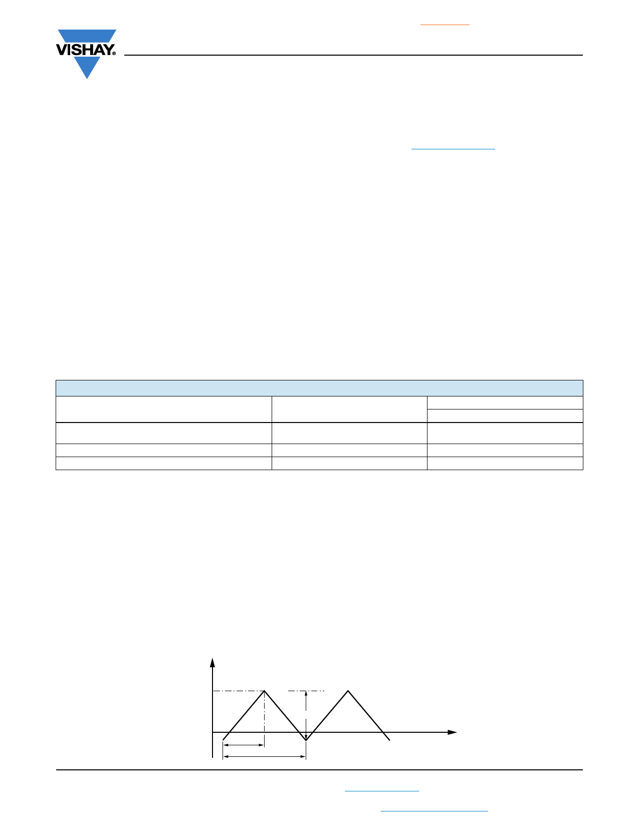
Example
C = 330 nF - 63 V used for the voltage signal shown in next drawing.
UP-P = 40 V; UP = 35 V; T1 = 100 μs; T2 = 200 μs
The ambient temperature is 35 °C
Checking conditions:
1. The peak voltage UP = 35 V is lower than 63 VDC
2. The peak-to-peak voltage 40 V is lower than 22 x 40 VAC = 113 UP-P
3. The voltage pulse slope (dU/dt) = 40 V/100 μs = 0.4 V/μs
This is lower than 60 V/μs (see specific reference data for each version)
4. The dissipated power is 16.2 mW as calculated with fourier terms
The temperature rise for wmax. = 3.5 mm and pitch = 5 mm will be 16.2 mW/3.0 mW/°C = 5.4 °C
This is lower than 15 °C temperature rise at 35 °C, according figure “Max. allowed component temperature rise”
5. Not applicable
6. Not applicable
Voltage Signal
Voltage
UP
UP-P
T1
T2
Time
Revision: 11-Jan-18
9
Document Number: 26032
For technical questions, contact: dc-film@vishay.com
THIS DOCUMENT IS SUBJECT TO CHANGE WITHOUT NOTICE. THE PRODUCTS DESCRIBED HEREIN AND THIS DOCUMENT
ARE SUBJECT TO SPECIFIC DISCLAIMERS, SET FORTH AT www.vishay.com/doc?91000
Share Link: 