AXK720127G 查看數據表(PDF) - Panasonic Corporation
零件编号
产品描述 (功能)
生产厂家
AXK720127G
Panasonic Corporation

AXK720127G Datasheet PDF : 11 Pages
| |||
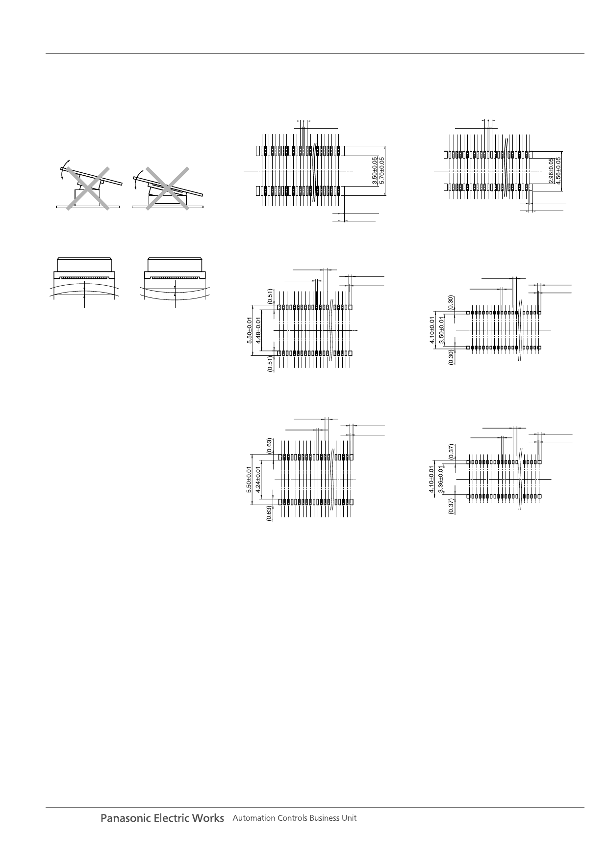
NOTES
1. As shown below, excess force
during insertion may result in damage
to the connector or removal of the
solder. Please be careful. Also, to
prevent connector damage please
confirm the correct position before
mating connectors.
AXK7, 8
1) Without soldering terminal
Socket
Recommended PC board pattern (TOP VIEW)
0.40±0.05
0.40±0.05
0.23±0.03
Header
Recommended PC board pattern (TOP VIEW)
0.40±0.05
0.23±0.03
0.40±0.05
2. Keep the PC board warp no more
than 0.03 mm in relation to the overall
length of the connector.
Max. 0.03 mm
Max. 0.03 mm
3. PC Boards and Recommended
Metal Mask Patterns
Connectors are mounted with high
density, with a pitch interval of 0.4 to 0.5
mm.
In order to reduce solder bridge and
other issues make sure the proper levels
of solder are used.
The figures to the right are recommended
metal mask patterns.
Please use them as a reference.
0.115±0.05
0.40±0.05
Recommended metal mask pattern
Metal mask thickness: Here, 150 µm
(Opening area ratio: 40 %)
0.40±0.01
0.20±0.01
0.35±0.01
0.10±0.01
Recommended metal mask pattern
Metal mask thickness: Here, 120 µm
(Opening area ratio: 50 %)
0.40±0.01
0.20±0.01
0.35±0.01
0.10±0.01
0.115±0.05
0.40±0.05
Recommended metal mask pattern
Metal mask thickness: Here, 150 µm
(Opening area ratio: 32 %)
0.40±0.01
0.20±0.01
0.35±0.01
0.10±0.01
Recommended metal mask pattern
Metal mask thickness: Here, 120 µm
(Opening area ratio: 40 %)
0.40±0.01
0.20±0.01
0.35±0.01
0.10±0.01
panasonic-electric-works.net/ac
Share Link: