AP65200MP-13(2014) 查看數據表(PDF) - Diodes Incorporated.
零件编号
产品描述 (功能)
生产厂家
AP65200MP-13 Datasheet PDF : 18 Pages
| |||
AP65200
Pin Descriptions
Pin
Name
BS
IN
SW
GND
FB
COMP
EN
SS
AGND
PAD
Pin Number
SO-8
SO-8EP
MSOP-8EP
U-DFN2626-10
Function
1
2
High-Side Gate Drive Boost Input. BS supplies the drive for the high-side N-Channel MOSFET a
0.01µF or greater capacitor from SW to BS to power the high side switch.
Power Input. IN supplies the power to the IC, as well as the step-down converter switches. Drive
2
3
IN with a 4.7V to 18V power source. Bypass IN to GND with a suitably large capacitor to eliminate
noise on the input to the IC. See Input Capacitor.
Power Switching Output. SW is the switching node that supplies power to the output. Connect the
3
4
output LC filter from SW to the output load. Note that a capacitor is required from SW to BS to
power the high-side switch.
4
5. 6
Ground
Feedback Input. FB senses the output voltage and regulates it. Drive FB with a resistive voltage
5
7
divider connected to it from the output voltage. The feedback threshold is 0.925V. See Setting the
Output Voltage.
Compensation Node. COMP is used to compensate the regulation control loop. Connect a series
6
8
RC network from COMP to GND. In some cases, an additional capacitor from COMP to GND is
required. See Compensation Components.
Enable Input. EN is a digital input that turns the regulator on or off. Drive EN high to turn on the
regulator; low to turn it off.
7
9
Attach EN to IN with a 100kΩ pull up resistor for automatic startup. With this configuration an
internal voltage clamp ensures that a safe voltage is set for Enable not to exceed the absolute
maximum voltage for this pin.
Soft-Start Control Input. SS controls the soft-start period. Connect a capacitor from SS to GND to
8
10
set the soft-start period. A 0.1µF capacitor sets the soft-start period to 15ms. To disable the soft-
start feature, leave SS floating.
NA
1
Analog GND
Exposed PAD for thermal performance improvement connect to GND
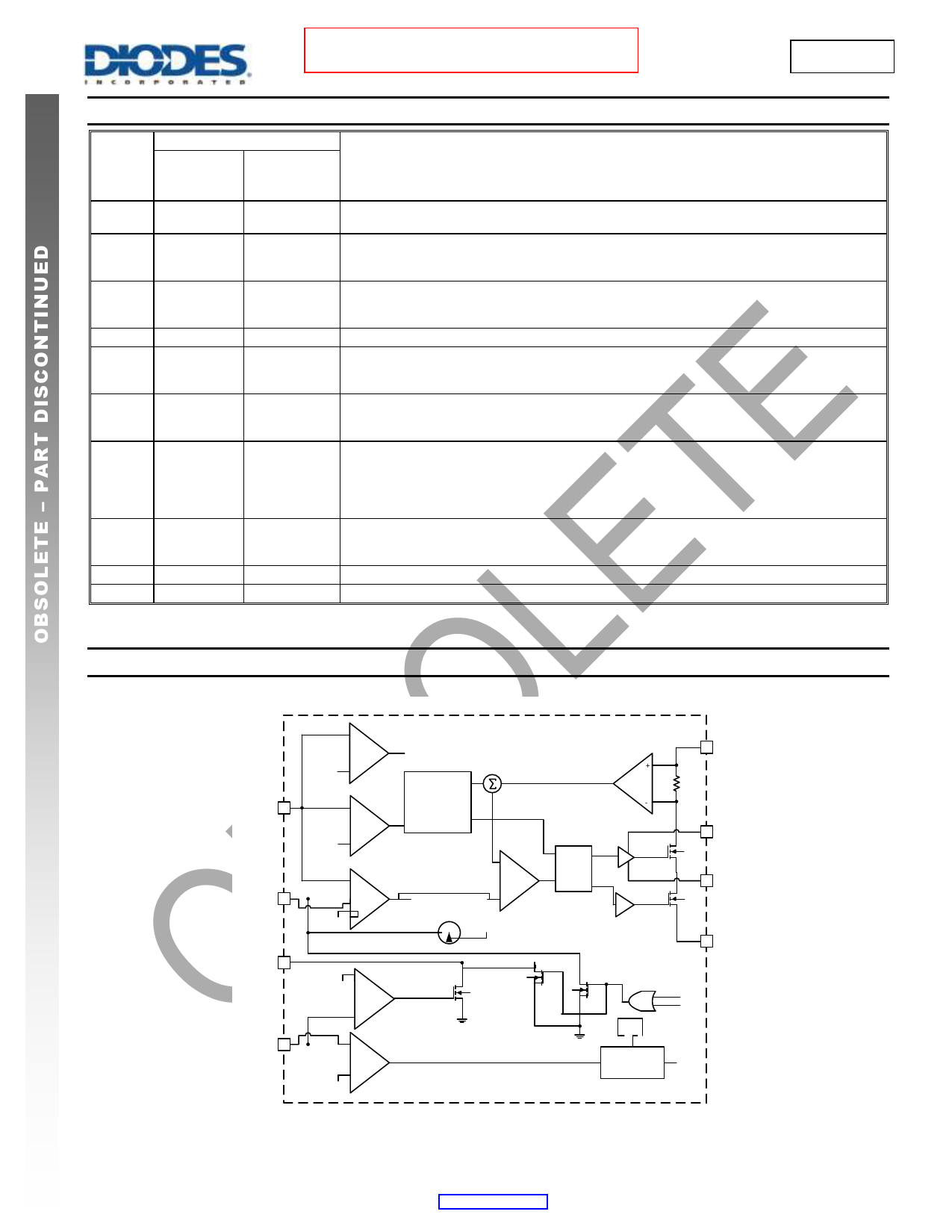
Functional Block Diagram
AP65200
Document number: DS35548 Rev. 6 - 2
2 of 18
www.diodes.com
January 2014
© Diodes Incorporated
Share Link: 