AD1846JP 查看數據表(PDF) - Analog Devices
零件编号
产品描述 (功能)
生产厂家
AD1846JP Datasheet PDF : 28 Pages
| |||
AD1846
(Continued from page 1)
AD1846
CS
A1
A0
WR
RD
DATA7:0
DBDIR
DBEN
PDRQ
CDRQ
PDAK
CDAK
INT
ADDRESS
DECODE
18
8
7
8
4
DIR 2
G
4
5
B
A
AEN
SA19:2
SA1
SA0
IOWC
IORC
DATA7:0
ISA BUS
DRQ<X>
DRQ<Y>
DAK<X>
DAK<Y>
IRQ<Z>
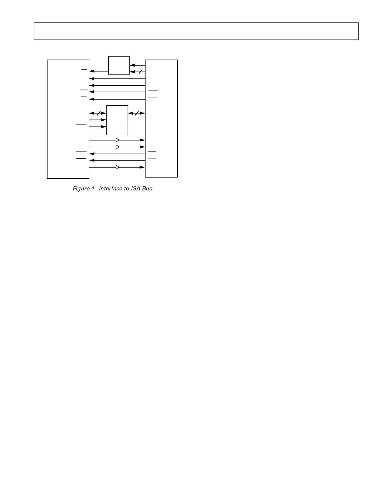
Figure 1. Interface to ISA Bus
The pair of 16-bit outputs from the ADCs is available over a
byte-wide bidirectional interface that also supports 16-bit digital
input to the DACs and control information. The AD1846 can
accept and generate 16-bit twos-complement PCM linear digital
data, 8-bit unsigned magnitude PCM linear data, and 8-bit
µ-law or A-law companded digital data.
The ∑∆ DACs are preceded by a digital interpolation filter. An
attenuator provides independent user volume control over each
DAC channel. Nyquist images and shaped quantization noise
are removed from the DACs’ analog stereo output by on-chip
switched-capacitor and continuous-time filters. Two stereo pairs
of auxiliary line-level inputs can also be mixed in the analog do-
main with the DAC output.
AUDIO FUNCTIONAL DESCRIPTION
This section overviews the functionality of the AD1846 and is
intended as a general introduction to the capabilities of the de-
vice. As much as possible, detailed reference information has
been placed in “Control Registers” and other sections. The user
is not expected to refer repeatedly to this section.
Analog Inputs
The AD1846 SoundPort Stereo Codec accepts stereo line-level
and mic-level inputs. LINE, MIC, and AUX1 inputs and post-
mixed DAC output analog stereo signals are multiplexed to the
internal programmable gain amplifier (PGA) stage.
The PGA following the input multiplexer allows independent
selectable gains for each channel from 0 to 22.5 dB in +1.5 dB
steps. The Codec can operate either in a global stereo mode or
in a global mono mode with left channel inputs appearing at
both channel outputs.
Analog Mixing
AUX1 and AUX2 analog stereo signals can be mixed in the ana-
log domain with the DAC output. Each channel of each auxil-
iary analog input can be independently gained/attenuated from
+12 dB to –34.5 dB in –1.5 dB steps or completely muted. The
post mixed DAC output is available on OUT externally and as
an input to the ADCs.
Even if the AD1846 is not playing back data from its DACs, the
analog mix function can still be active.
Analog-to-Digital Datapath
The AD1846 ∑∆ ADCs incorporate a fourth order modulator.
A single pole of passive filtering is all that is required for anti-
aliasing the analog input because of the ADC’s high 64 times
oversampling ratio. The ADCs include linear phase digital deci-
mation filters that low-pass filter the input to 0.4 ϫ FS. (“FS’’ is
the word rate or “sampling frequency”). ADC input overrange
conditions will cause bits to be set that can be read.
Each channel of the mic inputs can be amplified digitally by
+18 dB to compensate for the voltage swing differences between
line levels and typical condenser microphone levels. This +18
dB digital gain is enabled with the same control bits (LMGE
and RMGE) as the +20 dB analog gain in the AD1848.
Digital-to-Analog Datapath
The ∑∆ DACs contain a programmable attenuator and a low-
pass digital interpolation filter. The anti-imaging interpolation
filter oversamples by 64 and digitally filters the higher frequency
images. The attenuator allows independent control of each
DAC channel from 0 dB to –94.5 dB in 1.5 dB steps plus full
mute. The DACs’ ∑∆ noise shapers also oversample by 64 and
convert the signal to a single bit stream. The DAC outputs are
then filtered in the analog domain by a combination of switched-
capacitor and continuous-time filters. They remove the very
high frequency components of the DAC bitstream output. No
external components are required. Phase linearity at the analog
output is achieved by internally compensating for the group
delay variation of the analog output filters.
Changes in DAC output attenuation take effect only on zero
crossings, thereby eliminating “zipper” noise. Each channel has
its own independent zero-crossing detector and attenuator
change control circuitry. A timer guarantees that requested vol-
ume changes will occur even in the absence of an input signal
that changes sign. The time-out period is 8 milliseconds at a
48 kHz sampling rate and 48 milliseconds at an 8 kHz sampling
rate. (Time out [ms] ≈ 384/FS [kHz].)
Digital Mixing
Stereo digital output from the ADCs can be mixed digitally with
the input to the DACs. Digital output from the ADCs going out
of the data port is unaffected by the digital mix. Along the digi-
tal mix datapath, the 16-bit linear output from the ADCs is
attenuated by an amount specified with control bits. Both chan-
nels of the monitor data are attenuated by the same amount.
(Note that internally the AD1846 always works with 16-bit
PCM linear data, digital mixing included; format conversions
take place at the input and output.)
REV. A
–9–
Share Link: 