MURB1660CTG(2006) 查看數據表(PDF) - ON Semiconductor
零件编号
产品描述 (功能)
生产厂家
MURB1660CTG Datasheet PDF : 4 Pages
| |||
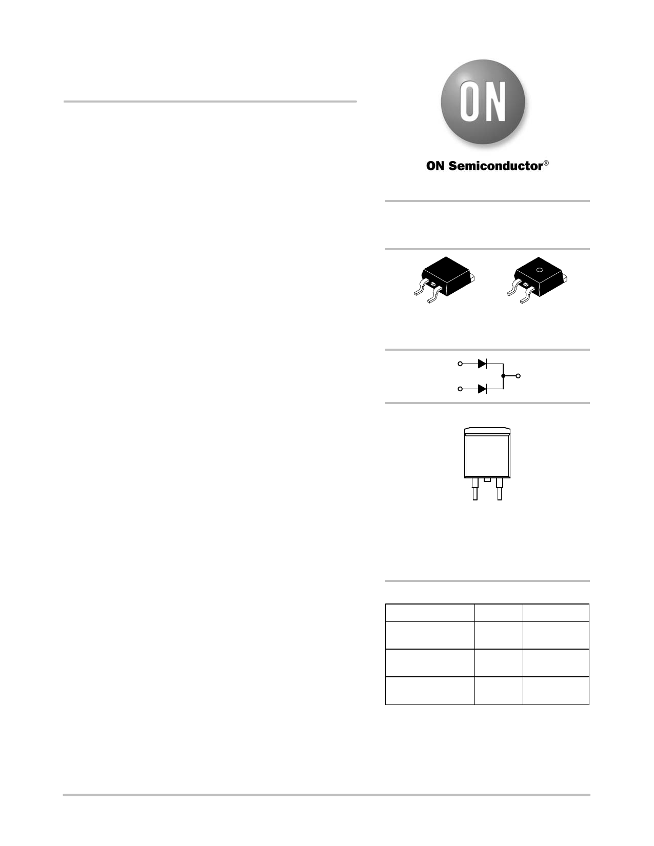
MURB1660CT
Preferred Device
SWITCHMODEt
Power Rectifier
D2PAK Power Surface Mount Package
These state−of−the−art devices are designed for use in switching
power supplies, inverters, and as free wheeling diodes.
Features
• Package Designed for Power Surface Mount Applications
• Ultrafast 60 Nanosecond Recovery Times
• 175°C Operating Junction Temperature
• Epoxy Meets UL 94 V−0 @ 0.125 in
• High Temperature Glass Passivated Junction
• High Voltage Capability to 600 V
• Low Leakage Specified @ 150°C Case Temperature
• Short Heat Sink Tab Manufactured − Not Sheared!
• Similar in Size to Industrial Standard TO−220 Package
• Pb−Free Packages are Available
Mechanical Characteristics:
• Case: Epoxy, Molded, Epoxy Meets UL 94 V−0
• Weight: 1.7 Grams (Approximately)
• Finish: All External Surfaces Corrosion Resistant and Terminal
Leads are Readily Solderable
• Lead and Mounting Surface Temperature for Soldering Purposes:
260°C Max. for 10 Seconds
• Device Meets MSL1 Requirements
• ESD Ratings: Machine Model, C >400 V
Human Body Model, 3B >8000 V
MAXIMUM RATINGS (Per Leg)
Rating
Symbol Value Unit
Peak Repetitive Reverse Voltage
Working Peak Reverse Voltage
DC Blocking Voltage
VRRM
600
V
VRWM
VR
Average Rectified Forward Current
(Rated VR, TC = 150°C) Total Device
IF(AV)
8.0
A
16
Peak Repetitive Forward Current
IFM
(Rated VR, Square Wave, 20 kHz, TC = 150°C)
16
A
Non−Repetitive Peak Surge Current
(Surge Applied at Rated Load Conditions
Halfwave, Single Phase, 60 Hz)
IFSM
100
A
Operating Junction and Storage Temperature TJ, Tstg −65 to °C
Range
+175
Stresses exceeding Maximum Ratings may damage the device. Maximum
Ratings are stress ratings only. Functional operation above the Recommended
Operating Conditions is not implied. Extended exposure to stresses above the
Recommended Operating Conditions may affect device reliability.
© Semiconductor Components Industries, LLC, 2006
1
July, 2006 − Rev. 7
http://onsemi.com
ULTRAFAST RECTIFIER
16 AMPERES, 600 VOLTS
1
4
3
D2PAK
4
CASE 418B
STYLE 3
1
3
MARKING DIAGRAM
AY WW
U1660G
AKA
A
Y
WW
U1660
G
AKA
= Assembly Location
= Year
= Work Week
= Specific Device Code
= Pb−Free Package
= Diode Polarity
ORDERING INFORMATION
Device
MURB1660CT
MURB1660CTG
MURB1660CTT4
MURB1660CTT4G
Package
D2PAK
D2PAK
(Pb−Free)
D2PAK
D2PAK
(Pb−Free)
Shipping†
50 Units/Rail
50 Units/Rail
800/Tape & Reel
800/Tape & Reel
†For information on tape and reel specifications,
including part orientation and tape sizes, please
refer to our Tape and Reel Packaging Specification
Brochure, BRD8011/D.
Preferred devices are recommended choices for future use
and best overall value.
Publication Order Number:
MURB1660CT/D
Share Link: 