RK73H1ELTP10R7F 查看數據表(PDF) - KOA Speer Electronics, Inc.
零件编号
产品描述 (功能)
生产厂家
RK73H1ELTP10R7F Datasheet PDF : 3 Pages
| |||
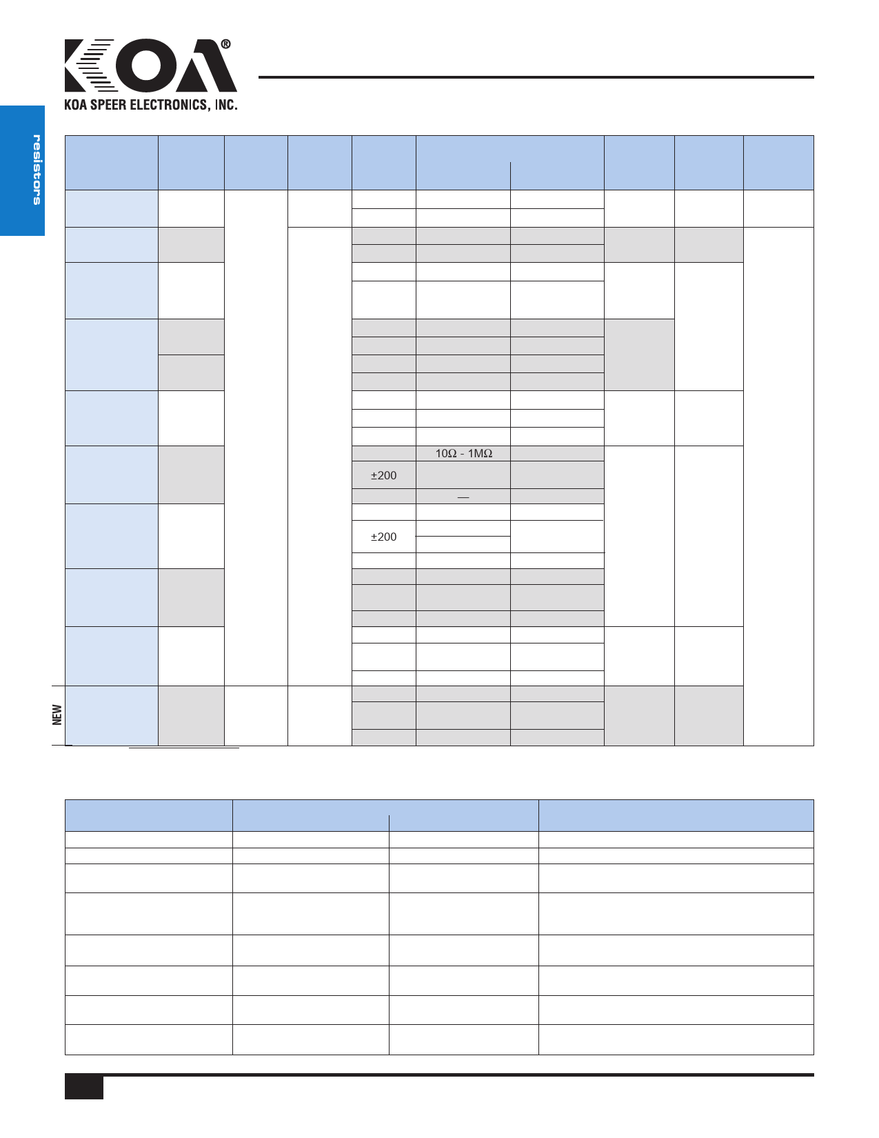
RK73H
applications and ratings
precision 0.5%, 1% tolerance
thick film chip resistor
Part
Designation
RK73H1F
(01005)
RK73H1H
(0201)
Power
Rating
0.03W
0.05W
Rated
Ambient
Temp.
Rated
Terminal
Part
Temp.
—
T.C.R.
(x10-6/K)
±200
±250
±200
±400
Resistance Range
D±0.5%
E-24, E-96
—
—
10Ω - 1MΩ
—
F±1%
E-24, E-96
100kΩ - 2MΩ1
10Ω - 91kΩ1
10Ω - 10MΩ1
1.0Ω - 9.1Ω1
Maximum
Working
Voltage
20V
25V
Maximum Operating
Overload Temperature
Voltage
Range
30V
-55°C to
+125°C
50V
RK73H1E
(0402)
0.1W
±100
±200
10Ω - 1MΩ
10Ω - 1MΩ
—
1.0Ω - 9.76Ω
50V
1.02MΩ - 10MΩ
RK73H1J
(0603)
0.1W
0.125W
±100
1.02kΩ - 1MΩ 1.02kΩ - 1MΩ
±200
±100
—
10Ω - 1kΩ
1.02MΩ - 10MΩ
10Ω - 1kΩ
75V
±200
—
1.0Ω - 9.76Ω
100V
RK73H2A
(0805)
0.25W
70°C
±100
±200
±400
10Ω - 1MΩ
—
—
10Ω - 1MΩ
1.0Ω - 9.76Ω
1.02MΩ - 10MΩ
150V
200V
RK73H2B
(1206)
0.25W
125°C
±100
±200
±400
±100
10Ω - 1MΩ
—
—
10Ω - 1MΩ
10Ω - 1MΩ
1.0Ω - 9.76Ω
1.02MΩ - 5.6MΩ
5.62MΩ - 10MΩ
10Ω - 1MΩ
-55°C to
+155°C
RK73H2E
(1210)
0.5W
±200
—
1.0Ω - 9.76Ω
—
1.02MΩ - 5.6MΩ 200V
400V
±400
—
5.62MΩ - 10MΩ
RK73HW2H/2H
(2010)
0.75W
±100
±200
±400
10Ω - 1MΩ
—
—
10Ω - 1MΩ
1.0Ω - 9.76Ω
1.02MΩ - 5.6MΩ
5.62MΩ - 10MΩ
±100
10Ω - 1MΩ
10Ω - 1MΩ
RK73HW3A/3A
(2512)
1.0W
±200
±400
—
1.0Ω - 9.76Ω
1.02MΩ - 5.6MΩ
200V
400V
—
5.62MΩ - 10MΩ
±100
10Ω - 1MΩ
10Ω - 1MΩ
RK73HW3A2
(2512)
2.0W
––
95°C
±200
—
1.0Ω - 9.76Ω
1.02MΩ - 5.6MΩ
200V
400V
±400
—
5.62MΩ - 10MΩ
Rated voltage = √Power rating x resistance value or max. working voltage, whichever is lower 1 1F: 10~2MΩ: E-24. 1H: 1.0~9.1, 1M~10MΩ: E-24. If any questions arise whether to use the “Rated Ambient Temperature”
or the “Rated Terminal Part Temperature,” please give priority to the “Rated Terminal Part Temperature.” Prior to use and for
environmental applications
more details refer to “Introduction of the derating curves based on the terminal part temperature” in the beginning of the catalog.
While using under high power, the temperature of the product may increase depending on the condition of heat dissipation from
Performance Characteristics
PCB. Be sure to check the terminal part temperature as well as precautions to use on delivery specification before use.
Parameter
Requirement ∆ R (%+0.1Ω)
Limit
Typical
Test Method
Resistance
Within specified tolerance
—
25°C
T.C.R.
Within specified T.C.R.
—
+25°C/-55°C and +25°C/+125°C
Overload (Short time)
±2%
±1%: 1F
±0.5% Another
Rated Voltage x 2.5 for 5 seconds
(1E, 2B, W3A2: Rated Voltage x 2 for 5 seconds)
Resistance to Soldering Heat
±1%: 1F ~ W3A2
(10Ω≤R≤1MΩ); ±3%: 1H ~
W3A2 (R<10Ω, R>1MΩ)
±0.5%: 1F ~ W3A2
(10Ω<R<1MΩ); ±1%: 1H ~
W3A2 (R<10Ω, R>1MΩ)
260°C ± 5°C, 10 seconds ± 1 second
Rapid Change of Temperature
±1%: 1F
±0.5% Another
±0.5%: 1F
±0.3% Another
-55°C (30 minutes), +125°C (30 minutes), 100 cycles
Moisture Resistance
±2%: 1J, 2A, 2B
±3%: Another
±0.75%: 1J, 2A, 2B;
40°C ± 2°C, 90%-95% RH, 1000 hours, 1.5 hr ON,
±1.5%:1F, ±1%: Another 0.5 hr OFF cycle
Endurance at 70°C
±2%: 1J, 2A, 2B
±3%: Another
±0.75%: 1J, 2A, 2B
±1%: Another
70°C ± 2°C, 1000 hours, 1.5 hr ON, 0.5 hr OFF cycle
High Temperature Exposure
±1%
±0.5%: 1F
±0.3%: Another
+125°C, 1000 hours: 1F; +155°C, 1000 hours: 1E, 1H,
1J, 2A, 2B, 2E, 2H/W2H, 3A/W3A/W3A2
Specifications given herein may be changed at any time without prior notice. Please confirm technical specifications before you order and/or use.
11/03/17
16 KOA Speer Electronics, Inc. • 199 Bolivar Drive • Bradford, PA 16701 • USA • 814-362-5536 • Fax: 814-362-8883 • www.koaspeer.com
Share Link: 