RT8105 查看數據表(PDF) - Richtek Technology
零件编号
产品描述 (功能)
生产厂家
RT8105 Datasheet PDF : 12 Pages
| |||
RT8105
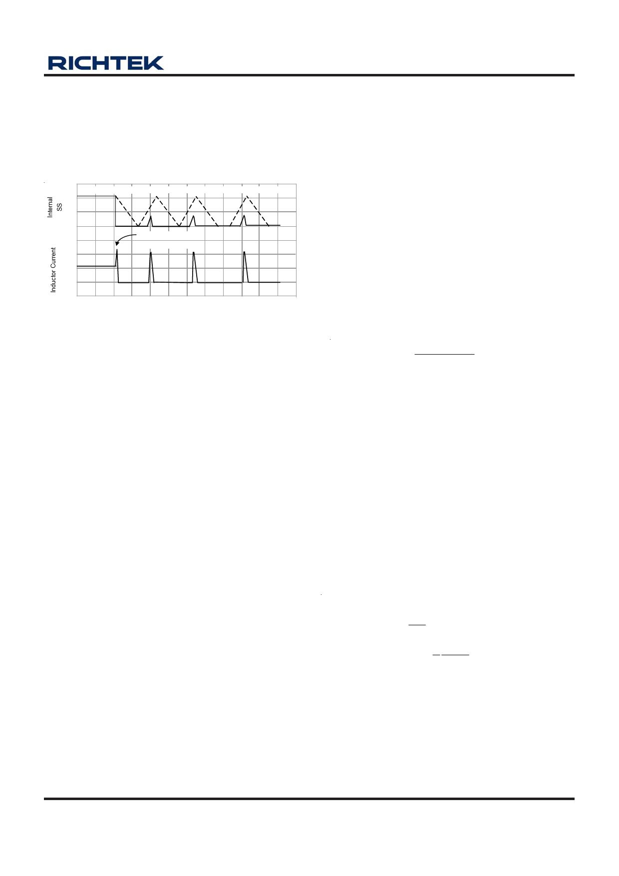
try to restart in a hiccupped way. Figure 3 shows the
hiccupped over current protection. Only four times of
hiccup is allowed in over current protection. If over current
condition still exist after four times of hiccup, controller
will be latched.
COUNT = 1
4V
2V
0V
COUNT = 2 COUNT = 3
OVERLOAD
APPLIED
COUNT = 4
0A
T0 T1
T2
T3
T4
TIME
Figure 3. Hiccupped Over Current Protection
Over Voltage Protection (OVP)
The feedback voltage is continuously monitored for over
voltage protection. When OVP is tripped, LGATE will go
high and UGATE will go low to discharge the output
capacitor.
RT8105 provides full-time over voltage protection whenever
soft start completes or not.
Over voltage protection has two operating conditions:
before soft start completes and after soft start completes.
Each condition is described as follows.
Before soft start completes, the typical OVP threshold is
137.5% of the internal reference voltage VREF. RT8105
provides non-latched OVP before soft start completes.
The controller will return to normal operation if over voltage
condition is removed.
After soft start completes, however, the OVP threshold is
typically 162.5% of VREF. RT8105 provides latched OVP
after soft start completes. The controller can only be reset
if VCC POR is exceeded again.
Under Voltage Protection (UVP)
The feedback voltage is also monitored for under voltage
protection. The under voltage protection has 15us triggered
delay. When UVP is tripped, both UGATE and LGATE will
go low. Unlike OCP, UVP is not a latched protection;
controller will always try to restart in a hiccupped way.
Enable/Disable
The controller can be disabled by pulling OPS pin to
ground. The enable/disable function can be implemented
by connecting a MOSFET or BJT to OPS pin. It is
recommended to use small signal MOSFET/BJT to
implement the enable/disable function.
Output Inductor Selection
The selection of output inductor depends on the efficiency,
output current and operating frequency. Low inductance
value can have fast transient response, but the associated
large current ripple will cause large output ripple voltage
and decrease the efficiency.
In general, a 20% to 40% of inductor ripple current
percentage (ΔIL / IOUT) is preferred in practical application.
The minimum inductance can be determined as follows :
L
=
(VIN
−
VOUT
)×
VIN
VOUT
× fS ×
ΔIL
Where :
VIN = Input voltage
VOUT = Output voltage
ΔIL = Inductor current ripple
fS = Switching frequency
Output Capacitor Selection
The selection of output capacitor depends on the inductor
ripple current, the output ripple voltage and the amount of
voltage under shoot during transient. The output ripple
voltage is a function of both the capacitance and the
equivalent series resistance (ESR) rC. The output ripple
voltage can be expressed as follows :
ΔVOUT = ΔVOR + ΔVOC
ΔVOUT
=
ΔIL
× rc
+
1
CO
∫ t2
t1
ic
dt
ΔVOUT
=
ΔIL
× ΔIL
× rc
+
1
8
VOUT
COL
(1− D)T 2
S
where ΔVOR is caused by ESR, and ΔVOC is related to the
capacitance value.
For electrolytic capacitor application, major of the output
voltage ripple is typically contributed by the ESR.
Therefore, the output voltage ripple can be simplified as
follows :
ΔVOUT = ΔIL x rC
DS8105-03 April 2011
www.richtek.com
9
Share Link: 