AN826 ТЪЦуюІТЋИТЊџУАе№╝ѕPDF№╝Ѕ - Microchip Technology
жЏХС╗Ху╝ќтЈи
С║ДтЊЂТЈЈУ┐░ (тіЪУЃй)
ућЪС║Дтјѓт«Х
AN826
Microchip Technology

AN826 Datasheet PDF : 14 Pages
| |||
The Q of a crystal is not normally specified in the data
sheets. The Q of standard crystals fall between values
of 20,000 and 200,000 [5]. By way of comparison, the
Q of a good LC tuned circuit is on the order of 200 [2].
The very high Q of a crystal contributes to the high fre-
quency stability of a crystal oscillator.
Series vs Parallel Resonant Crystals
There is no difference in the construction of a series
resonant crystal and a parallel resonant crystal, which
are manufactured exactly alike. The only difference
between them is that the desired operating frequency
of the parallel resonant crystal is set 100 ppm or so
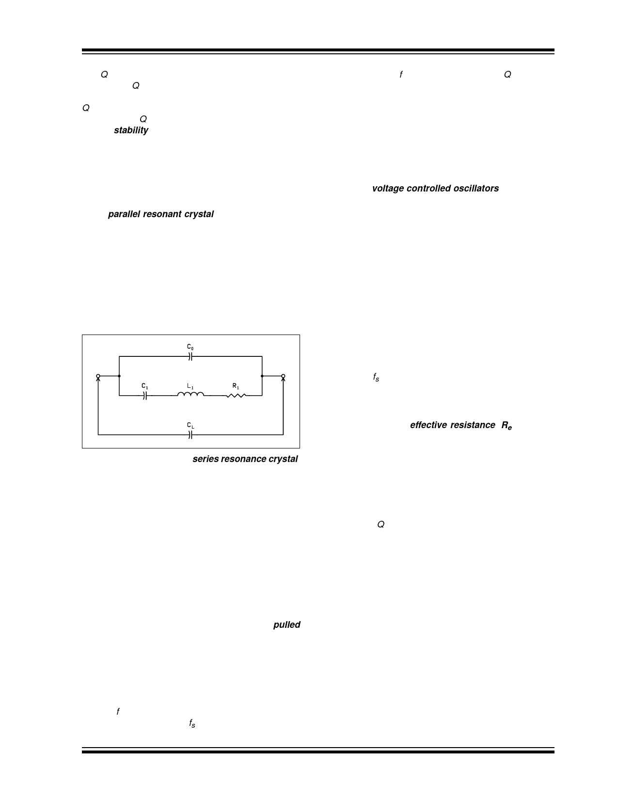
above the series resonant frequency. Parallel reso-
nance means that a small capacitance, called load
capacitance (CL), of 12 to 32 pF (depending on the
crystal) should be placed across the crystal terminals to
obtain the desired operating frequency [6]. Figure 11
shows load capacitance in parallel with the crystal
equivalent circuit.
FIGURE 11: LOAD CAPACITANCE ACROSS
THE CRYSTAL
Therefore, when ordering a series resonance crystal,
load capacitance CL is not specified. It is implied as
zero. These crystals are expected to operate in a circuit
designed to take advantage of the crystals mostly resis-
tive nature at series resonance.
On the other hand, a parallel resonant crystal has a
load capacitance specified. This is the capacitive load
the crystal expects to see in the circuit and thus operate
at the frequency specified. If the load capacitance is
something other than what the crystal was designed
for, the operating frequency will be offset from the spec-
ified frequency.
Crystal Pulling
Series or parallel resonance crystals can be pulled
from their specified operating frequency by adjusting
the load capacitance (CL) the crystal sees in the circuit.
An approximate equation for crystal pulling limits is:
Рѕєf
=
fs
№БФ
№БГ
-2---(--C-----0C----+-1---C-----L---)№БИ№БХ
Where Рѕєf is the pulled crystal frequency (also known as
the load frequency) minus fs.
┬Е 2002 Microchip Technology Inc.
AN826
The limits of Рѕєf depend on the crystal Q and stray
capacitance of the circuit. If the shunt capacitance,
motional capacitance, and load capacitance is known,
the average pulling per pF can be found using:
ppm РЂё pF
=
-----C-----1---├Ќ-----1---0---6------
2(C0 + CL)2
Crystal pulling can be helpful when we wish to tune the
circuit to the exact operating frequency desired. Exam-
ples are voltage controlled oscillators (VCO) where
the load capacitance is changed with a varactor diode
which can be adjusted electrically. Another example is
pulling the crystal for Frequency Shift Keying (FSK)
modulation. One capacitance value equates to an
operating frequency to represent a binary 1. A second
capacitance value equates to an operating frequency
to represent a binary 0. This is the method the
rfPIC12C509AF uses for FSK modulation.
Crystal pulling can be harmful if the printed circuit
board exhibits stray capacitance and inadvertently
pulls the crystal off the desired operating frequency.
Equivalent Series Resistance
The Equivalent Series Resistance (ESR) is the resis-
tance the crystal exhibits at the series resonant fre-
quency (fs). It should not be confused with motional
resistance (R1). ESR is typically specified as a maxi-
mum resistance value (in ohms).
The resistance of the crystal at any load capacitance
(CL) is called the effective resistance, Re. It can be
found using [5]:
Re
=
R
1
№БФ
№БГ
C-----L--C--+--L---C----0-№БИ№БХ
2
CRYSTAL OSCILLATORS
We see that a quartz crystal is a tuned circuit with a
very high Q. This and many other desirable attributes
make the crystal an excellent component choice for
oscillators. Crystal oscillators are recognizable from
their LC oscillator counterparts [4]. For the Pierce and
Colpitts oscillators, the crystal replaces the inductor in
the corresponding LC tuned circuit oscillators. Not sur-
prisingly, the crystal will appear inductive in the circuit.
Recall the crystalРђЎs equivalent circuit of Figure 8 when
reviewing crystal oscillator operation.
Crystal Oscillator Operation
Upon start-up, the amplitude of oscillation builds up to
the point where nonlinearities in the amplifier decrease
the loop gain to unity. During steady-state operation,
the crystal, which has a large reactance-frequency
slope as we saw in Figure 10, is located in the feedback
network at a point where it has the maximum influence
on the frequency of oscillation. A crystal oscillator is
DS00826A-page 7
Share Link: