AN826 ТЪЦуюІТЋИТЊџУАе№╝ѕPDF№╝Ѕ - Microchip Technology
жЏХС╗Ху╝ќтЈи
С║ДтЊЂТЈЈУ┐░ (тіЪУЃй)
ућЪС║Дтјѓт«Х
AN826
Microchip Technology

AN826 Datasheet PDF : 14 Pages
| |||
internal capacitance, and stray capacitance (CS). The
product design engineer selects the values of capaci-
tors C2 and C3 to match the crystal CL using the below
equation:
CL
=
----C----2---C----3----
C2 + C3
+
CS
Stray capacitance can be assumed to be in the range
of 2 to 5 pF. PCB stray capacitance can be minimized
by keeping traces as short as possible. A desirable
characteristic of the Pierce oscillator is the effects of
stray reactances and biasing resistors appear across
the capacitors C2 and C3 in the circuit rather than the
crystal.
If the circuit load capacitance does not equal the crystal
CL, the operating frequency of the Pierce oscillator will
not be at the specified crystal frequency. For example,
if the crystal CL is kept constant and the values of C2
and C3 are increased, the operating frequency
approaches the crystal series resonant frequency (i.e,
the operating frequency of the oscillator decreases).
Care should be used in selecting values of C2 and C3.
Large values increase frequency stability but decrease
the loop gain and may cause oscillator start-up prob-
lems. Typically the values of C2 and C3 are equal. A
trimmer capacitor can be substituted for C2 or C3 in
order to manually tune the Pierce oscillator to the
desired frequency. Select capacitors with a low temper-
ature coefficient such as NP0 or C0G types.
Colpitts Crystal Oscillator
The Colpitts crystal oscillator (Figure 16) is a parallel
resonant circuit for Fundamental mode crystals [3]. The
Colpitts is designed to look into a high impedance
across the crystal terminals [6]. The series combination
of C2 and C3, in parallel with the effective transistor
input capacitance, form the crystal loading capacitance
[3]. The effects of stray reactances appear across the
crystal. The biasing resistors are also across the crys-
tal, which can degrade performance as mentioned in
the LC version.
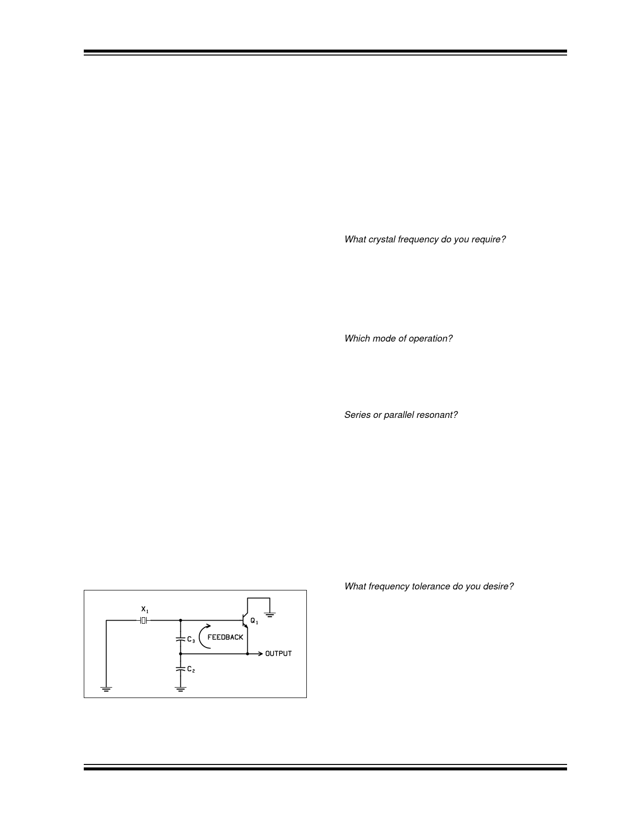
FIGURE 16: COLPITTS CRYSTAL
OSCILLATOR
In the particular Colpitts configuration shown in Figure
16, the capacitive divider off the tuned circuit provides
the feedback as in a classic LC Colpitts. However, the
crystal grounds the gate at the series resonant fre-
┬Е 2002 Microchip Technology Inc.
AN826
quency of the crystal, permitting the loop to have suffi-
cient gain to sustain oscillations at that frequency only
[4]. This configuration is useful because only one pin is
required to connect the external crystal to the device.
The other terminal of the crystal is grounded.
A trimmer capacitor can be placed in series with the
crystal to manually tune the Colpitts oscillator to the
desired frequency.
SPECIFYING A CRYSTAL
Now that we know how a crystal behaves in an oscilla-
tor circuit, letРђЎs review the specification questions asked
by the crystal manufacturer:
What crystal frequency do you require?
This is the frequency stamped on the crystal package.
It is the desired operational crystal frequency for the cir-
cuit. It depends on the mode of operation (fundamental
or overtone, series or parallel resonant), and load
capacitance. Recall that parallel resonant crystals
operate at the specified frequency at the specified load
capacitance (CL) that you request.
Which mode of operation?
Fundamental or overtone. This Application Note
focused primarily on Fundamental mode since the
rfPIC and PICmicro MCU oscillators generally operate
below 30 MHz, which is the upper frequency limit of AT-
cut quartz crystals.
Series or parallel resonant?
This tells the crystal manufacturer how the crystal will
be used in the oscillator circuit. Series resonant crys-
tals are used in oscillator circuits that contain no reac-
tive components in the feedback loop. Parallel
resonant crystals are used in oscillator circuits that con-
tain reactive components. As mentioned, there is no
difference in the construction of a series or parallel res-
onant crystal.
For the Pierce and Colpitts oscillators reviewed in this
Application Note, the crystal is used at its parallel reso-
nant frequency. Therefore, a load capacitance must be
specified in order for the crystal to operate at the fre-
quency stamped on the package.
What frequency tolerance do you desire?
This is the allowable frequency deviation plus and
minus the specified crystal frequency. It is specified in
parts per million (PPM) at a specific temperature, usu-
ally +25 degrees C.
The designer must determine what frequency toler-
ance is required for the product design. For example, a
PICmicro device in a frequency insensitive application
the frequency tolerance could be 50 to 100 ppm. For a
rfPIC device, the crystal frequency is multiplied up to
the transmit frequency. Therefore, the tolerance will be
multiplied. The tolerance required depends on the radio
frequency regulations of the country the product will be
used. Tolerances of 30 ppm or better are generally
DS00826A-page 9
Share Link: