BWR-5/6-3.3/7-D12L1 查看數據表(PDF) - DATEL Data Acquisition products
零件编号
产品描述 (功能)
生产厂家
BWR-5/6-3.3/7-D12L1
DATEL Data Acquisition products

BWR-5/6-3.3/7-D12L1 Datasheet PDF : 12 Pages
| |||
XWR Series
33W, DUAL OUTPUT, MIXED-VOLTAGE DC/DC CONVERTERS
Absolute Maximum Ratings
Input Voltage:
Continuous:
"D12" Models
"D24" Models
"D48" Models
Transient (100msec): "D12" Models
"D24" Models
"D48" Models
23 Volts
42 Volts
81 Volts
25 Volts
50 Volts
100 Volts
Input Reverse-Polarity Protection ➁
"D12" Models
"D24" Models
"D48" Models
Input Current must be limited. 1 minute
duration. Fusing recommended.
6 Amps
4 Amps
2 Amps
Output Current ➁
Current limited. Devices can withstand
an indefinite output short circuit.
On/Off Control (Pin 4) Max. Voltages
Referenced to –Input (pin 2)
+VIN
Storage Temperature
–40 to +120°C
Lead Temperature (Soldering, 10 sec.) +300°C
These are stress ratings. Exposure of devices to any of these conditions may adversely
affect long-term reliability. Proper operation under conditions other than those listed in the
Performance/Functional Specifications Table is not implied, nor recommended.
TECHNICAL NOTES
5V & 3.3V Regulation
The BWR 33 Watt Series converters are designed such that both the 5V and
3.3V outputs share a common regulation feedback control loop. Though the
feedback loop is influenced by both outputs, the 3.3 Volt output is dominant.
As a result, the 3.3 Volt regulation (1%) is superior to the 5 Volt regulation (1.5%).
The converters are specified for load regulation of 10% to 100% loading and
for no-load to 100% loading. Operation below 10% of full load mandates
an increase in the regulation tolerance of ±0.5% for 3.3 Volt output and an
increase of ±1% for the 5 Volt output. A slight increase in switching noise
may also be observed for operation below 10% loading.
Operation with a full load on 3.3 Volt output and light to no load on 5 Volt
output is the most demanding for +5V regulation. Under such conditions the
internal "bleeder" circuit is activated to provide an internal load thereby keep-
ing regulation within the published specifications. The bleeder is activated
gradually so as not to cause any erratic behavior on the converters outputs. A
slight degradation in efficiency will occur while this internal load is activated.
Filtering and Noise Reduction
The BWR 33 Watt Series Converters achieve their rated ripple and noise
specifications with the use of 1µF output capacitors. In critical applications,
input/output noise may be further reduced by installing additional external
I/O capacitors. Input capacitors should be selected for bulk capacitance,
low ESR and high rms-ripple-current ratings. Output capacitors should be
selected for low ESR and appropriate frequency response. All caps should
have appropriate voltage ratings and be located as close to the converter
as possible.
Start-Up Time
The VIN to VOUT start-up time is the interval of time where the input voltage
crosses the turn-on threshold point, and the fully loaded output voltage enters
and remains within its specified accuracy band. Actual measured times will
vary with input source impedance, external input/output capacitance, and the
slew rate of the input voltages. The BWR-5/6-3.3/7 Series implements a
soft start circuit that limits the duty cycle of the PWM controller at power up,
thereby limiting the Input Inrush current.
The On/Off Control to VOUT start-up time assumes the converter has its
nominal input voltage applied but is turned off via the On/Off Control pin.
The specification defines the interval between the time at which the converter
is turned on and the fully loaded output voltage enters and remains within
its specified accuracy band. Similar to the VIN to VOUT start-up, the On/Off
Control to VOUT start-up time is also governed by the internal soft start
circuitry and external load capacitance.
Input Overvoltage/Undervoltage Shutdown and Start-Up Threshold
Under normal start-up conditions, devices will not begin to regulate until
the ramping-up input voltage exceeds the Start-Up Threshold Voltage (35V
for "D48" models). Once operating, devices will not turn off until the input
voltage drops below the Undervoltage Shutdown limit (34V for "D48" models).
Subsequent re-start will not occur until the input is brought back up to the
Start-Up Threshold. This built in hysteresis prevents any unstable on/off
situations from occurring at a single input voltage.
Input voltages exceeding the input overvoltage shutdown specification listed
in the Performance/Functional Specifications will cause the device to shut-
down. A built-in hysteresis of 0.6 to 1.6 Volts for all models will not allow the
converter to restart until the input voltage is sufficiently reduced.
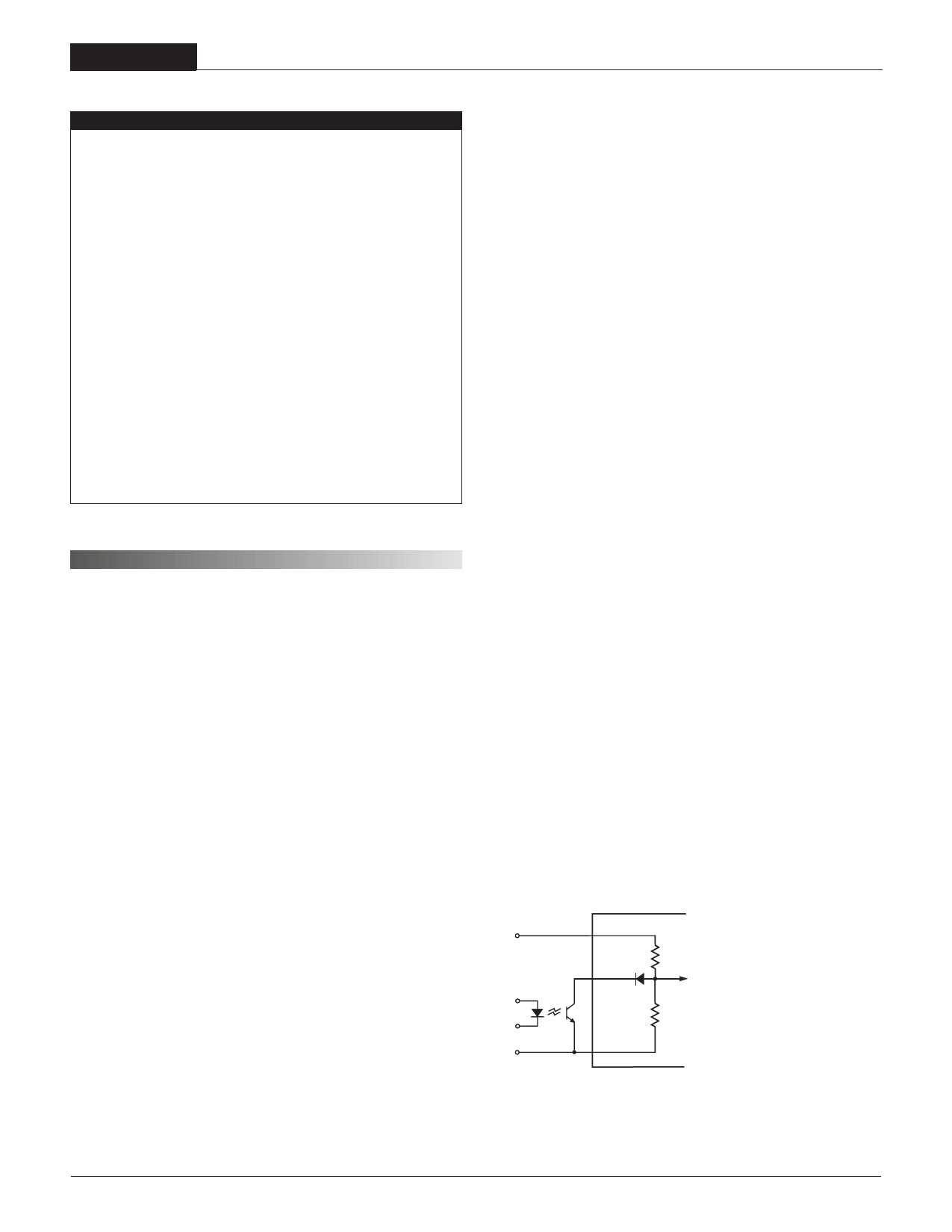
On/Off Control
The On/Off Control (pin 4) may be used for remote on/off operation. As
shown in Figure 1, the control pin is referenced to the –Input (pin 2) and will
be internally pulled to a high state. The standard BWR model (no suffix) is
designed so that it is enabled when the control pin is left open and disabled
when the control pin is pulled low (less than +0.8V relative to –Input).
Dynamic control of the on/off function is best accomplished with a mechanical
relay or an open-collector/open-drain circuit (optically isolated if appropriate).
The drive circuit should be able to sink approximately 1 mA for logic low.
The on/off control function is designed such that the converter can be
disabled while the input power is ramping up, and then "released" once the
input has stabilized.
1 +INPUT
RA
4
D12 RA = 34.8kΩ, RB = 6.83kΩ
ON/OFF
CONTROL
D24 RA = 100kΩ, RB = 9.74kΩ
D48 RA = 100kΩ, RB = 4.53kΩ
RB
2 –INPUT
Figure 1. Internal Circuitry for On/Off Control
4
Share Link: