MBRF20100CT 查看數據表(PDF) - TSC Corporation
零件编号
产品描述 (功能)
生产厂家
MBRF20100CT Datasheet PDF : 2 Pages
| |||
CREAT BY ART
Pb
RoHS
COMPLIANCE
MBRF2035CT - MBRF20200CT
20.0 AMPS. Isolated Schottky Barrier Rectifiers
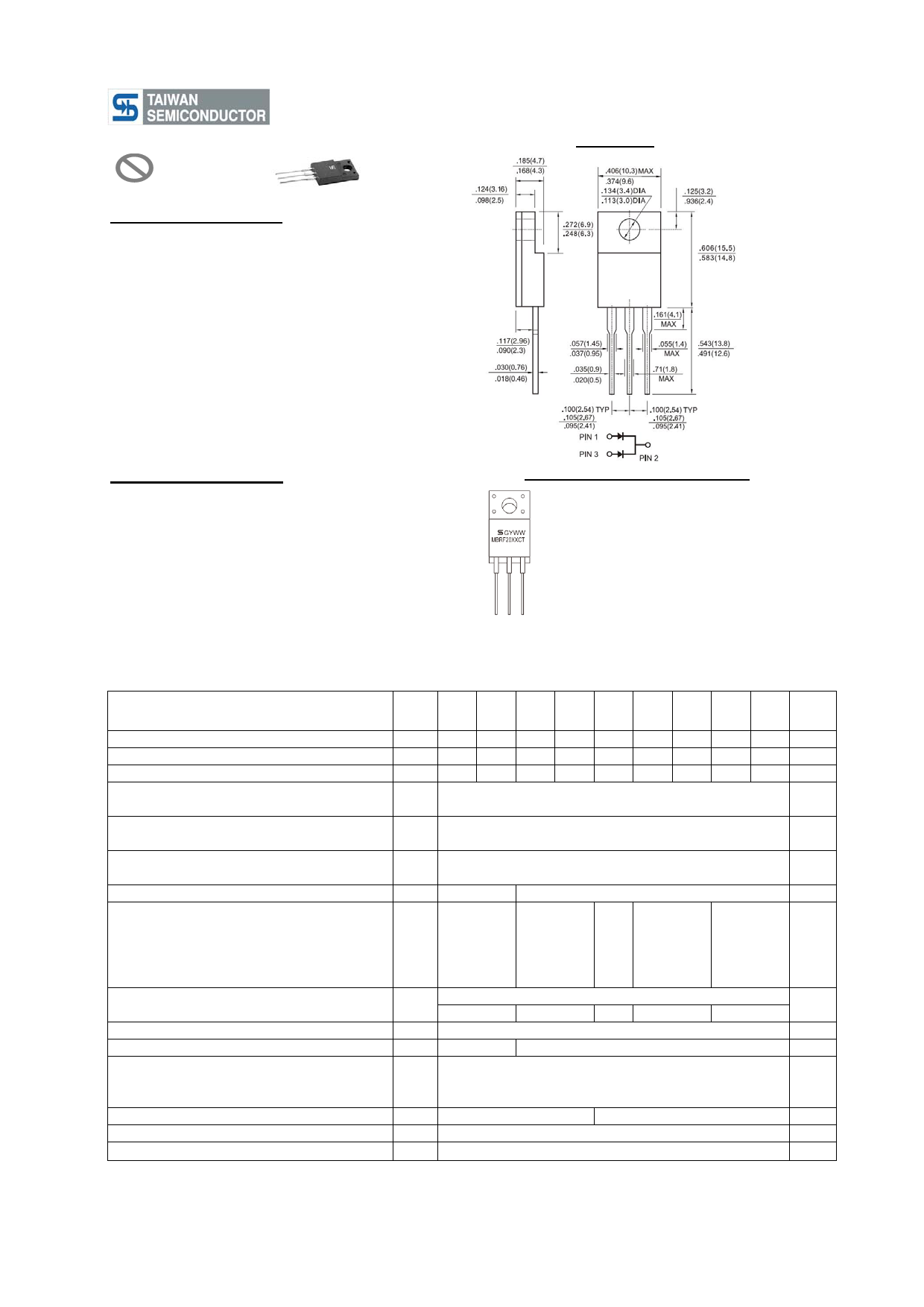
ITO-220AB
Features
UL Recognized File # E-326243
Plastic material used carriers Underwriters
Laboratory Classification 94V-0
Metal silicon junction, majority carrier conduction
Low power loss, high efficiency
High current capability, low forward voltage drop
High surge capability
For use in low voltage, high frequency inverters,
free wheeling, and polarity protection applications
Guard-ring for overvoltage protection
High temperature soldering guaranteed:
260℃/10 seconds, at terminals
Green compound with suffix "G" on packing
code & prefix "G" on datecode
Mechanical Data
Case:ITO-220AB molded plastic body
Terminals: Pure tin plated, lead free, solderable
per MIL-STD-750, Method 2026
Polarity: As marked
Mounting position:Any
Mounting torque: 5 in. - lbs, max
Weight: 1.7 grams
Dimensions in inches and (millimeters)
Marking Diagram
MBRF20XXCT
= Specific Device Code
G
= Green Compound
Y
= Year
WW
= Work Week
Maximum Ratings and Electrical Characteristics
Rating at 25 ℃ ambient temperature unless otherwise specified.
Single phase, half wave, 60 Hz, resistive or inductive load.
For capacitive load, derate current by 20%
Type Number
Maximum Repetitive Peak Reverse Voltage
Maximum RMS Voltage
Maximum DC Blocking Voltage
MBRF MBRF MBRF MBRF MBRF MBRF MBRF MBRF MBRF
Symbol 2035 2045 2050 2060 2080 2090 20100 20150 20200 Unit
CT CT CT CT CT CT CT CT CT
VRRM
35
45
50
60
80
90 100 150 200
V
VRMS
24
31
35
42
56
63
70 105 140
V
VDC
35
45
50
60
80
90 100 150 200
V
Maximum Average Forward Rectified Current
at Tc=135℃
IF(AV)
20
A
Peak Repetitive Forward Current (Rated VR,
Square Wave, 20KHz) at Tc=135℃
IFRM
20
A
Peak Forward Surge Current, 8.3 ms Single Half Sine-
wave Superimposed on Rated Load (JEDEC method)
IFSM
150
A
Peak Repetitive Reverse Surge Current (Note 1)
IRRM
1
0.5
A
Maximum Instantaneous Forward Voltage (Note 2)
IF=10A, TA=25℃
0.80
0.80
0.80
0.85
0.95
IF=10A, TA=125℃
IF=20A, TA=25℃
IF=20A, TA=125℃
VF
0.57
0.70
0.65
0.75
0.85
0.84
0.95
1.00
0.95
1.05
0.72
0.85
0.75
0.85
0.95
Maximum Reverse Current @ Rated VR TA=25 ℃
TA=125 ℃
IR
15
0.1
10
30
5
2
Voltage Rate of Change (Rated VR)
dV/dt
10000
Typical Junction Capacitance
Cj
400
310
RMS Isolation Voltage (MBRF Type Only) from
Terminals to Heatsink with t=1.0 Second,
VISO
RH≦30%
4500(Note 3)
3500(Note 4)
1500(Note 5)
Typical Thermal Resistance Per Leg
Operating Temperature Range
RθjC
1.5
3.5
TJ
- 65 to + 150
Storage Temperature Range
TSTG
- 65 to + 150
Note 1: 2.0uS Pulse Width, f=1.0KHz
Note 2: Pulse Test : 300uS Pulse Width, 1% Duty Cycle
Note 3: Clip Mounting (on case), where lead does not overlap heatsink with 0.11" offset
Note 4: Clip Mounting (on case), where lead does not overlap heatsink
Note 5: Screw Mounting screw, where diameter is ≦4.9mm(0.19")
Version:K11
V
mA
V/us
pF
V
OC/W
OC
OC
Share Link: 