LA7853 查看數據表(PDF) - SANYO -> Panasonic
零件编号
产品描述 (功能)
生产厂家
LA7853 Datasheet PDF : 4 Pages
| |||
LA7853
On-Chip Functions
[Horizontal Block]
[Vertical Block]
• AFC
• Vertical OSC
• Horizontal OSC
• Vertical sawtooth wave generator
• X-ray protector
• Sampling type DC voltage control
• Horizontal phase shift
• AFC sawtooth wave generator
• Horizontal pulse duty setting
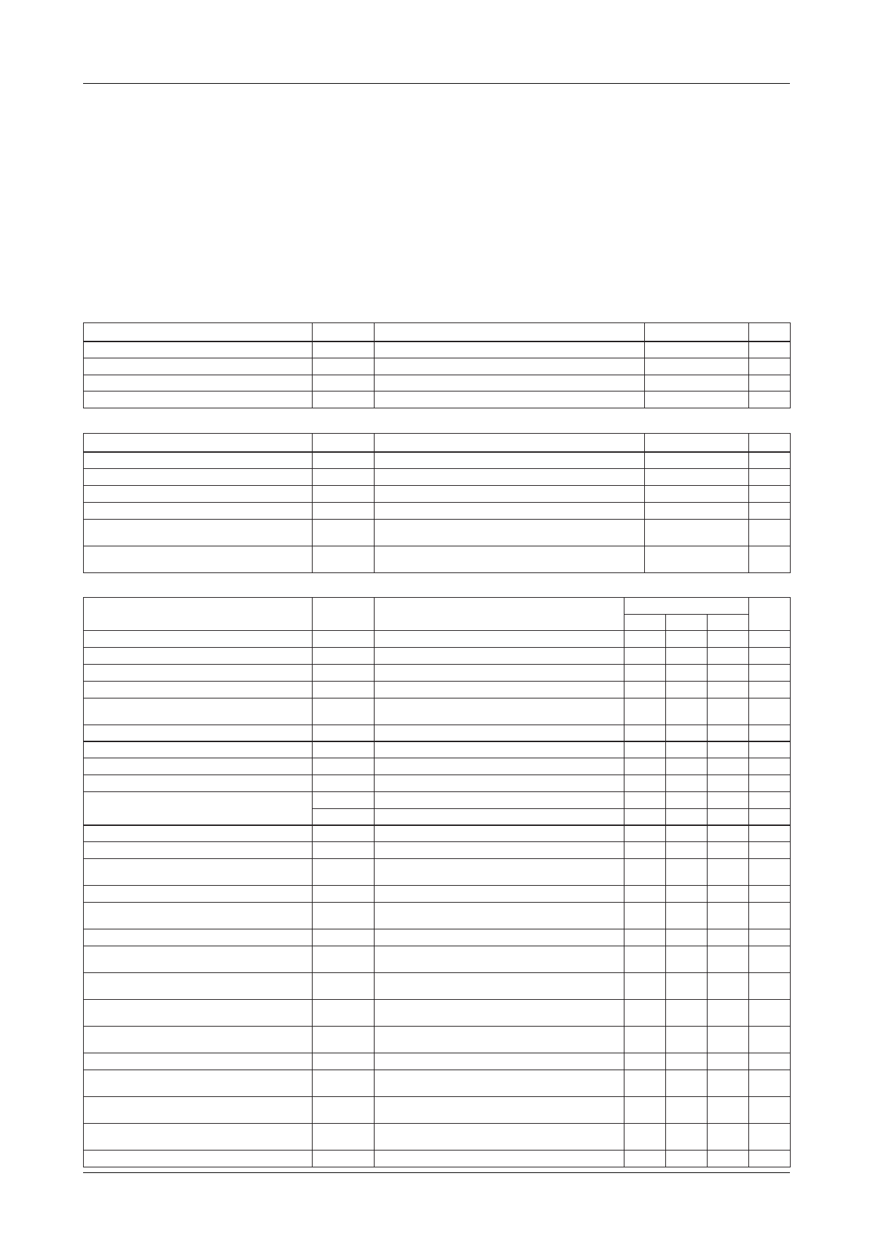
Specifications
Maximum Ratings at Ta = 25˚C
Parameter
Symbol
Maximum supply voltage
Allowable power dissipation
Operating temperature
Storage temperature
V11, V22
Pd max
Topr
Tstg
Ta≤65˚C
Operating Conditions at Ta = 25˚C
Parameter
Symbol
Recommended supply voltage
Operating voltage range
Recommended vertical pulse input peak value
Operating vertical pulse input peak value range
Recommended horizontal pulse input peak
value
Operating horizontal pulse input peak value
range
V11, V22
V11, V22
VPULSE
VPULSE
HPULSE
HPULSE
Operating Characteristics at Ta = 25˚C
Conditions
Conditions
Parameter
Symbol
Conditions
VCC11 current drain
VCC22 current drain
Vertical frequency pull-in range
Vertical free-running frequency
Increased/reduced voltage characteristic of
vertical frequency
Midpoint control threshold level
Vertical OSC start voltage
Temparature characteristic of vertical frequency
Vertical driver amplification factor
Horizontal AFC DC loop gain
Horizontal free-running frequency
Horizontal OSC start voltage
Increased/reduced voltage characteristic of
horizontal frequency
Horizontal OSC warm-up drift
Temperature characteristic of horizontal
frequency
Horizontal output drive current
Increased/reduced voltage characteristic of
phase shifter delay time
Temperature characteristic of phase shifter
delay time
Increased/reduced voltage characteristic of
phase shifter pulse width
Temperature characteristic of phase shifter
pulse width
AFC phase comparison center time
Increased/reduced voltage characteristic of AFC
phase comparison center time
Temperature characteristic of AFC phase
comparison center time
Comparison waveform generating input
operation voltage
pin 14 voltage at hold-down operation start
I11
I22
VP IN
fV
∆fVV
fv,st
Gv
IAFC+
IAFC–
fH
fH, st
∆fH, v
∆fH
I13
V5
V14
Vertical sync 60Hz
fV center 55Hz
V22=12±1V, 55Hz at 12V
Ta=–10 to +60˚C
fH center 15.734kHz
V11=12±1V, 15.734kHz at 12V
5s. to 30min. after application of power
Ta=–10 to +60˚C
V11=12±1V
Ta=–10 to +60˚C
V11=12±1V
Ta=–10 to +60˚C
15.734kHz after F.B.P. input
V11=12±1V
Ta=–10 to +60˚C
Ratings
Unit
14 V
780 mW
–20 to +85 ˚C
–55 to +125 ˚C
Ratings
12
9 to 13.5
5
2 to 6
Unit
V
V
Vp-p
Vp-p
5 Vp-p
2 to 6 Vp-p
Ratings
Unit
min typ max
12
30 mA
5
12 mA
19.0
23.0 Hz
50
60 Hz
–0.1
+0.1 Hz
3.8
–0.028
12
0.85
–1.6
–750
4.4
4.0
+0.028
18
1.6
–0.85
+750
4.0
V
V
Hz/˚C
dB
mA
mA
Hz
V
–50
+50 Hz
–50
+50 Hz
–2.9
+2.9 Hz/˚C
6.0
12.0 mA
–0.5
+0.5 %/V
–0.1
+0.1 %/˚C
–1.0
+1.0 %/V
–0.13
9.9
–1.5
+0.13 %/˚C
11.5 µs
+1.5 %/V
–0.2
+0.2 %/˚C
0.6
0.9 V
0.5
0.8 V
No.2873–2/4
Share Link: 