AS1712 وں¥çœ‹و•¸و“ڑè،¨ï¼ˆPDF) - austriamicrosystems AG
零ن»¶ç¼–هڈ·
ن؛§ه“پوڈڈè؟° (هٹں能)
ç”ںن؛§هژ‚ه®¶
AS1712
austriamicrosystems AG

AS1712 Datasheet PDF : 17 Pages
| |||
AS1710/AS1712
Data Sheet - Application Information
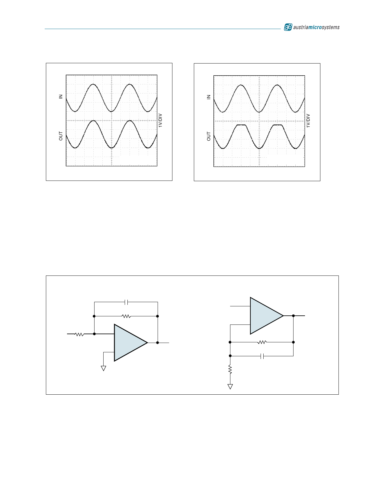
Figure 23. Rail-to-Rail Input/Output Range, 100kخ©
Figure 24. Rail-to-Rail Input/Output Range, 32خ©
VCC = 3.0V,
RLOAD = 100kخ©
2.5آµs/Div
VCC = 3.0V,
RLOAD = 32خ©
2.5آµs/Div
Note: The absolute maximum ratings (see page 3) for power dissipation and output short-circuit duration (10s, max)
must be adhered to since the output current can exceed 200mA (see Typical Operating Characteristics on
page 6).
Input Capacitance
The parallel-connected differential input stages for rail-to-rail operation results in relatively large input capacitance CIN
(6pF typ). This introduces a pole at frequency (2د€R′CIN)-1, where R′ is the parallel combination of the gain-setting
resistors for the inverting or non-inverting amplifier configuration (Figure 25). If the pole frequency is less than or com-
parable to the unity-gain bandwidth (10MHz), the phase margin is reduced, and the amplifier exhibits degraded AC
performance through either ringing in the step response or sustained oscillations.
Figure 25. Inverting and Non-inverting Amplifiers with Feedback Compensation
R
VIN
Inverting
CF
RF
–
AS1710
+
R′ = R II RF
RFCF = RCIN
VIN
Non-Inverting
+
AS1710
–
VOUT
RF
CF
R
VOUT
The pole frequency is 10MHz when R′ = 2kخ©. To maximize stability, R′ << 2kخ© is recommended.
To improve step response when R′ > 2kخ©, connect a small capacitor (CF) between the inverting input and output. CF
can be calculated by:
CF = 6(R/RF) [pf]
(EQ 6)
Where:
RF is the feedback resistor.
R is the gain-setting resistor.
www.austriamicrosystems.com
Revision 1.04
11 - 17
Share Link: