AS3843N13 查看數據表(PDF) - Astec Semiconductor => Silicon Link
零件编号
产品描述 (功能)
生产厂家
AS3843N13 Datasheet PDF : 20 Pages
| |||
AS384x
Current Mode Controller
Application Information
Section 1 Ð Theory of Operation
The AS3842/3/4/5 family of current-mode control
ICs are low cost, high performance controllers
which are pin compatible with the industry stan-
dard UC3842 series of devices. Suitable for
many switch mode power supply applications,
these ICs have been optimized for use in high
frequency off-line and DC-DC converters. The
AS3842 has been enhanced to provide signifi-
cantly improved performance, resulting in excep-
tionally better tolerances in power supply
manufacturing. In addition, all electrical charac-
teristics are guaranteed over the full 0 to 105¡C
temperature range. Among the many enhance-
ments are: a precision trimmed 2.5 volt reference
(+/Ð 1% of nominal at the error amplifier input), a
significantly reduced propagation delay from cur-
rent sense input to the IC output, a trimmed oscil-
lator for precise duty-cycle clamping, a modified
flip-flop scheme that gives a true 50% duty ratio
clamp on 3844/45 types, and an improved 5 V
regulator for better AC noise immunity. Further-
more, the AS3842 provides guaranteed perfor-
mance with current sense input below ground.
The advanced oscillator design greatly simplifies
synchronization. The device is more completely
specified to guarantee all parameters that impact
power supply manufacturing tolerances.
The functional block diagram of the AS3842 is
shown in Figure 1. The IC is comprised of the six
basic functions necessary to implement current
mode control; the under-voltage lockout; the refer-
ence; the oscillator; the error amplifier; the current
sense comparator/PWM latch; and the output.
The following paragraphs will describe the theory
of operation of each of the functional blocks.
1.1 Under-voltage lockout (UVLO)
The under-voltage lockout function of the
AS3842 holds the IC in a low quiescent current
(² 1 mA) ÒstandbyÓ mode until the supply voltage
(VCC) exceeds the upper UVLO threshold volt-
age. This guarantees that all of the ICÕs internal
circuitry are properly biased and fully functional
before the output stage is enabled. Once the IC
turns on, the UVLO threshold shifts to a lower
level (hysteresis) to prevent VCC oscillations.
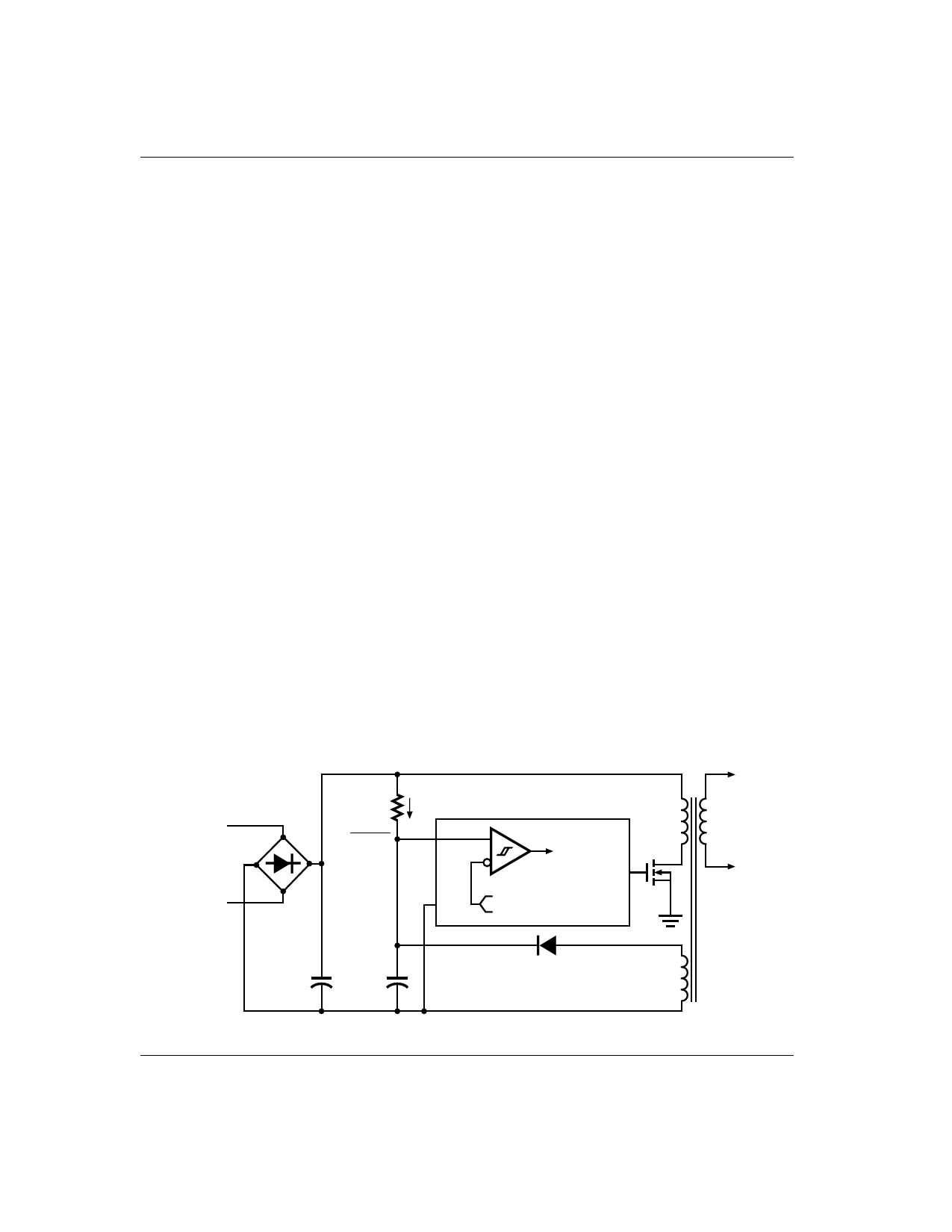
The low quiescent current standby mode of the
AS3842 allows ÒbootstrappingÓÐÑa technique
used in off-line converters to start the IC from the
rectified AC line voltage initially, after which power
to the IC is provided by an auxiliary winding off the
power supplyÕs main transformer. Figure 14 shows
a typical bootstrap circuit where capacitor (C) is
VDC
>1 mA
AC LINE
R
R < VDC MIN
1 mA
AS384x
7 VCC
PRI
SEC
IC ENABLE
6
OUT
5
GND
16 V/10 V (3842/4)
8.4 V/7.8 V (3843/5)
+
+
C
AUX
ASTEC Semiconductor
Figure 14. Bootstrap Circuit
10
Share Link: 