UF800F 查看數據表(PDF) - PACELEADER INDUSTRIAL
零件编号
产品描述 (功能)
生产厂家
UF800F Datasheet PDF : 2 Pages
| |||
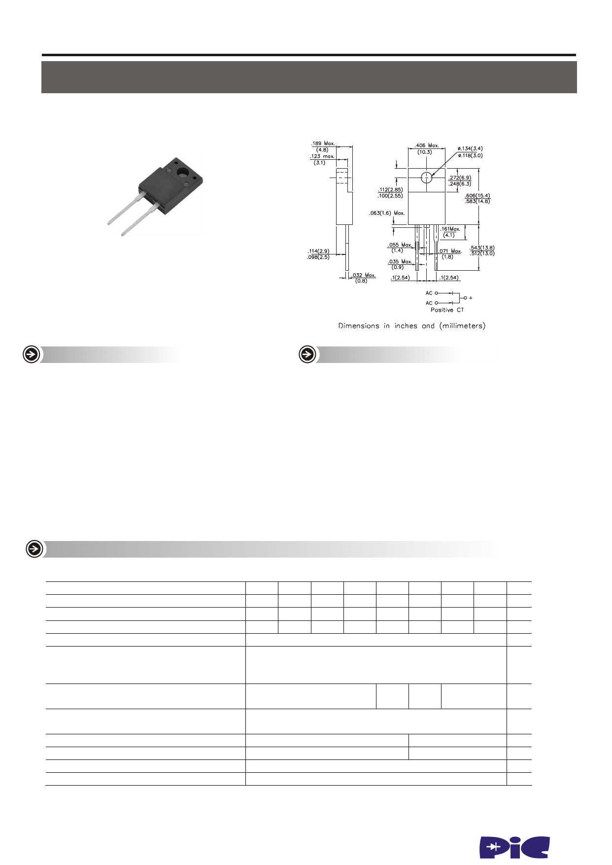
UF800F thru UF8010F
SURFACE MOSUUNPTERREFVAESRTSREEVCOOLVTEARGYERE5C0TTIFOIE1R000VOLTS
ULTRA FAST RECTIFIERS FORWARD CURRENT - 8.0 AMPERES
ITO-220AC
FEATURES
‧Plastic package has Underwriters Laboratory
Flammability Classification 94V-O Utilizing
Flame Retardant Epoxy Molding Compound
‧Exceeds environmental standards of MIL-S-19500/228
‧Low power loss, high efficiency
‧Low forward voltage, high current capability
‧High surge capacity
‧Ultra Fast recovery times, high voltage
‧High temperature soldering : 260OC / 10 seconds at terminals
‧ Pb free product at available : 99% Sn above meet RoHS environment
substance directive request
MECHANICAL DATA
‧ Case:ITO-220AC full molded plastic package
‧Terminals: Lead solderable per MIL-STD-202, Method 208
‧Polarity: As marked
‧Mounting Position: Any
‧Weight: 0.08 ounce, 2.26 gram
MAXIMUM RATIXGS AND ELECTRICAL CHARACTERISTICS @TA=25°C unless otherwise specified
Ratings at 25 OC J ambient temperature unless otherwise specified. Single phase, half wave, 60Hz, resistive or inductive load.
For capacitive load, derate current by 20%
UF800F UF801F UF802F UF803F UF804F UF806F UF808F UF8010F UNI TS
M aximum Recurren t Peak Rev erse Vo ltage
50
100
200
300
400
600
800
1000
V
Max imum RM S Voltage
35
70
140
210
280
420
560
700
V
Maximum DC Blocking Voltage
Maximum Average Forward Rectified Current at Tc=100°C
50
100
200
300
400
600
800
1000
V
8.0
A
Peak Forward Surge Current,
8.3 ms single half sine -wave
125
A
superimposed on rated load (JEDEC method)
Maximum Instantaneous Forward Voltage
at 8.0 A per element
1.0
1.3
1.5
1.7
V
Maximum DC Reverse Current (Note 1) Ta=25°C
at Rated DC Blocking Voltage
Ta=125°C
10
Aµ
500
Typical Junction Capacitance (Note 1)
Maximum Reverse Recovery Time (Note 2)
80
50
pF
50
75
nS
Typical Thermal Resistance Note RθJC
15
C° /W
Operating and Storage Temperature Range TJ
NOTES:
-55 to +150
C°
1. Reverse Recovery Test Conditions: IF=0.5A, IR=1A, Irr=0.25A
2. Measured at 1 MHz and applied reverse voltage of 4.0 VDC
3. Thermal resistance from junction to ambient and from junction to lead length 0.375"(9.5mm) P.C.B. mounted
www.paceleader.tw
1
Share Link: 