ML9041 查看數據表(PDF) - Oki Electric Industry
零件编号
产品描述 (功能)
生产厂家
ML9041 Datasheet PDF : 55 Pages
| |||
¡ Semiconductor
ML9041
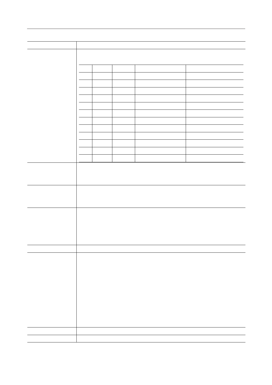
Symbol
CSR
SSR
V1, V2, V3A, V3B, V4
BEB
Description
The input pin to select the transfer direction of the common signal output data.
Refer to the Expansion Instruction Codes section about the AS bit.
CSR duty AS bit
shift direction
arbitrator's common pin
L
1/9
L
1/9
L 1/12
L 1/12
L 1/17
L 1/17
H
1/9
H
1/9
H 1/12
H 1/12
H 1/17
H 1/17
L
COM1 Æ COM9
H
COM2 Æ COM9, COM1
L
COM1 Æ COM12
H
COM2 Æ COM12, COM1
L
COM1 Æ COM17
H
COM2 Æ COM17, COM1
L
COM9 Æ COM1
H
COM8 Æ COM1, COM9
L
COM12 Æ COM1
H COM11 Æ COM1, COM12
L
COM17 Æ COM1
H COM16 Æ COM1, COM17
COM9
COM1
COM12
COM1
COM17
COM1
COM1
COM9
COM1
COM12
COM1
COM17
The input pin to select the transfer direction of the segment signal output data.
“L”: Data transfer from SEG1 to SEG100
“H”: Data transfer from SEG100 to SEG1
The pins to output bias voltages to the LCD.
For 1/4 bias : The V2 and V3B pins are shorted.
For 1/5 bias : The V3A and V3B pins are shorted.
The input pin to enable or disable the voltage multiplier circuit.
“L” disables the voltage multiplier circuit. “H” enables the voltage multiplier circuit.
The voltage multiplier circuit doubles the input voltage VIN and outputs it to the V5IN pin.
The voltage multiplier circuit can be used only when generating a level lower than GND.
VIN
V5, V5IN
VC
VCC
The pin to input voltage to the voltage multiplier.
The pins to supply the LCD drive voltage.
The LCD drive voltage is supplied to the V5 pin when the voltage multiplier is not used
(BEB = 0) and the internal contrast adjusting circuit is also not used. At this time, the
V5IN pin should be open.
The LCD drive voltage is supplied to the V5IN pin when the voltage multiplier is not used
(BEB = 0) but the internal contrast adjusting circuit is used. At this time, the V5 pin
should be open.
When the voltage multiplier is used (BEB = 1), the V5IN and V5 pins should be open (the
multiplied voltage is output to the V5IN pin). In this case, the internal contrast adjusting
circuit is used automatically.
The pin to connect the positive pin of the capacitor for the voltage multiplier.
The pin to connect the negative pin of the capacitor used for the voltage multiplier.
5/54
Share Link: 