NCP1012 查看數據表(PDF) - ON Semiconductor
零件编号
产品描述 (功能)
生产厂家
NCP1012 Datasheet PDF : 23 Pages
| |||
NCP1010, NCP1011,
NCP1012, NCP1013,
NCP1014
Self-Supplied Monolithic
Switcher for Low Standby-
Power Offline SMPS
The NCP101X series integrates a fixed−frequency current−mode
controller and a 700 V MOSFET. Housed in a PDIP−7 or SOT−223
package, the NCP101X offers everything needed to build a rugged and
low−cost power supply, including soft−start, frequency jittering,
short−circuit protection, skip−cycle, a maximum peak current setpoint
and a Dynamic Self−Supply (no need for an auxiliary winding).
Unlike other monolithic solutions, the NCP101X is quiet by nature:
during nominal load operation, the part switches at one of the available
frequencies (65 − 100 − 130 kHz). When the current setpoint falls
below a given value, e.g. the output power demand diminishes, the IC
automatically enters the so−called skip−cycle mode and provides
excellent efficiency at light loads. Because this occurs at typically 1/4
of the maximum peak value, no acoustic noise takes place. As a result,
standby power is reduced to the minimum without acoustic noise
generation.
Short−circuit detection takes place when the feedback signal fades
away, e.g. in true short−circuit conditions or in broken Optocoupler
cases. External disabling is easily done either simply by pulling the
feedback pin down or latching it to ground through an inexpensive
SCR for complete latched−off. Finally soft−start and frequency
jittering further ease the designer task to quickly develop low−cost and
robust offline power supplies.
For improved standby performance, the connection of an auxiliary
winding stops the DSS operation and helps to consume less than
100 mW at high line. In this mode, a built−in latched overvoltage
protection prevents from lethal voltage runaways in case the
Optocoupler would brake. These devices are available in economical
8−pin dual−in−line and 4−pin SOT−223 packages.
http://onsemi.com
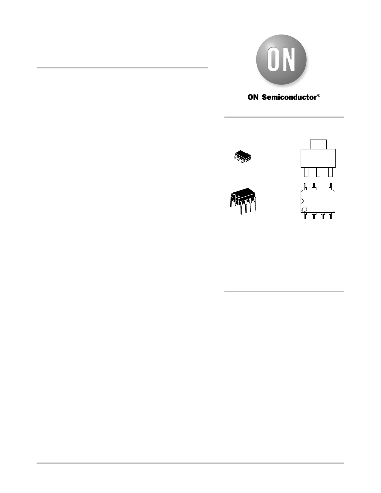
MARKING
DIAGRAMS
4
4
SOT−223
CASE 318E
1
ST SUFFIX
AYW
101xy G
G
1
8
1
PDIP−7
CASE 626A
AP SUFFIX
P101xAPyy
AWL
YYWWG
1
x
= Current Limit (0, 1, 2, 3, 4)
y
= Oscillator Frequency
A (65 kHz), B (100 kHz), C (130 kHz)
yy
= 06 (65 kHz), 10 (100 kHz), 13 (130 kHz)
A
= Assembly Location
WL = Wafer Lot
YY, Y = Year
WW, W = Work Week
G or G = Pb−Free Package
(Note: Microdot may be in either location)
ORDERING INFORMATION
See detailed ordering and shipping information in the package
dimensions section on page 21 of this data sheet.
Features
• Built−in 700 V MOSFET with Typical RDSon of 11 W
and 22 W
• Large Creepage Distance Between High−Voltage Pins
• Current−Mode Fixed Frequency Operation:
65 kHz – 100 kHz − 130 kHz
• Skip−Cycle Operation at Low Peak Currents Only:
No Acoustic Noise!
• Dynamic Self−Supply, No Need for an Auxiliary
Winding
• Internal 1.0 ms Soft−Start
• Latched Overvoltage Protection with Auxiliary
Winding Operation
• Frequency Jittering for Better EMI Signature
• Auto−Recovery Internal Output Short−Circuit
Protection
• Below 100 mW Standby Power if Auxiliary Winding
is Used
• Internal Temperature Shutdown
• Direct Optocoupler Connection
• SPICE Models Available for TRANsient Analysis
• These are Pb−Free and Halide−Free Devices
Typical Applications
• Low Power AC/DC Adapters for Chargers
• Auxiliary Power Supplies (USB, Appliances,TVs, etc.)
© Semiconductor Components Industries, LLC, 2014
1
September, 2014 − Rev. 23
Publication Order Number:
NCP1010/D
Share Link: 