AH31-RFID 查看數據表(PDF) - WJ Communications => Triquint
零件编号
产品描述 (功能)
生产厂家
AH31-RFID Datasheet PDF : 8 Pages
| |||
AH31
High Dynamic Range IF Amplifier
Product Information
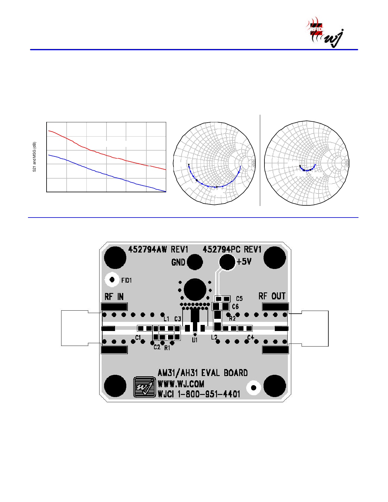
Typical Device Data
S-parameters (Vd = +5 V, Id = 150 mA, unmatched 50 Ω system).
• Measurements are shown for an unmatched packaged device with the data being de-embedded to the device leads.
• The amplifier requires a matching network at the input for proper operation. The amplifier is intrinsically well matched at the output and
ideally should “look” into 50 Ω. Any deviation from this can affect the linearity IP3 performance for the device.
25
22
19
16
13
10
0
S21 and Maximum Stable Gain
Maximum Stable Gain
S21
0.5
1
1.5
2
2.5
Frequency (GHz)
S11
3 GHz
-0.2
2 GHz
-0.4
3
1 GHz
Swp Max
3GHz
3.0
4.0
5.0
10.0
Swp Min
0.05GHz
S22
3 GHz
2 GHz 1 GHz
-0.2
-0.4
Swp Max
3GHz
3.0
4.0
5.0
10.0
Swp Min
0.05GHz
Application Circuit PC Board Layout
Circuit Board Material: .014” FR-4, 4 layers (other layers added for rigidity), .062” total thickness, 1 oz copper
Microstrip line details: width = .024”, spacing = .036”
Specifications and information are subject to change without notice
WJ Communications, Inc • Phone 1-800-WJ1-4401 • FAX: 408-577- 6621 • e-mail: sales@wj.com • Web site: www.wj.com
February 2004
Share Link: 