STLC7550TQFP 查看數據表(PDF) - STMicroelectronics
零件编号
产品描述 (功能)
生产厂家
STLC7550TQFP Datasheet PDF : 17 Pages
| |||
STLC7550
FUNCTIONAL DESCRIPTION
1 - TRANSMIT D/A SECTION
The functions included in the Tx D/A section are
detailed hereafter. 16-bit 2’s complement data for-
mat is used in the DAC channel.
1.1 - Transmit Low Pass Filters
The transmit low pass filter is basically an interpo-
lating filter including a sinx/x correction. It is a
combination of Finite Impulse Response filter (FIR)
and an Infinite Impulse Response filter (IIR). The
digital signal from the serial interface gets interpo-
lated by 2, 3, 4, 5 or 6 x Sampling Frequency (FS)
through the IIR filter. The signal is further interpo-
lated by 32 x FS x n (with n equal to 2, 3, 4, 5, 6)
through the IIR and FIR filter. The low pass filter is
followed by the DAC. The DAC is oversampled at
64, 96, 128, 160, 192 x FS. The oversampling ratio
is user selectable.
1.2 - D/A Converter
The oversampled D/A converter includes a second
order digital noise shaper, a one bit D/A converter
and a single pole analog low-pass filter.
The attenuation of the last output stage can be
programmed to 0dB, +6dB or infinite. The cut-off
frequency of the single pole switch-capacitor low-
pass filter is :
fc−3dB
=
OCLK
2 ⋅ π ⋅ 10
with OCLK = Oversampling Clock frequency.
Continuous-time filtering of the analog differential
output is necessary using an off-chip amplifier and
a few external passive components.
At least 79dB signal to noise plus distortion ratio can
be obtained in the frequency band of 0.425 x 9.6kHz
(with an oversampling ratio equal to 160).
2 - RECEIVE A/D SECTION
The different functions included in the ADC channel
section are described below. 16-bit 2’s complement
data format is used in the ADC.
2.1 - A/D Converter
The oversampled A/D converter is based on a
second order sigma-delta modulator. To produce
excellent common-mode rejection of unwanted sig-
nals, the analog signal is processed differentially
until it is converted to digital data. Single-ended
mode can also be used. The ADC is oversampled
at 64, 96, 128, 160 or 192 x FS. The oversampling
ratio is user selectable. At least -85dB SNDR can
be expected in the 0.425 x 9.6kHz bandwidth with
a -6dBr differential input signal and an oversam-
pling ratio equal to 160.
2.2 - Receive Low Pass Filter
It is a decimation filter. The decimation is performed
by two decimation digital filters : one decimation
FIR filter and one decimation IIR filter.
The purpose of the FIR filter is to decimate 32 times
the digital signal coming from the ADC modulator.
The IIR is a cascade of 5 biquads. It provides the
low-pass filtering needed to remove the noise re-
maining above half the sampling frequency. The
output of the IIR will be processed by the DSP.
3 - CLOCK GENERATOR
The master clock, MCLK is provided by the user
thanks to a crystal or external clock generator (see
Figure 1).
The MCLK could be equal to 36.864MHz
(MCM = 1). In that case thanks to the divider M x Q,
the STLC7550 is able to generate all V.34bis and
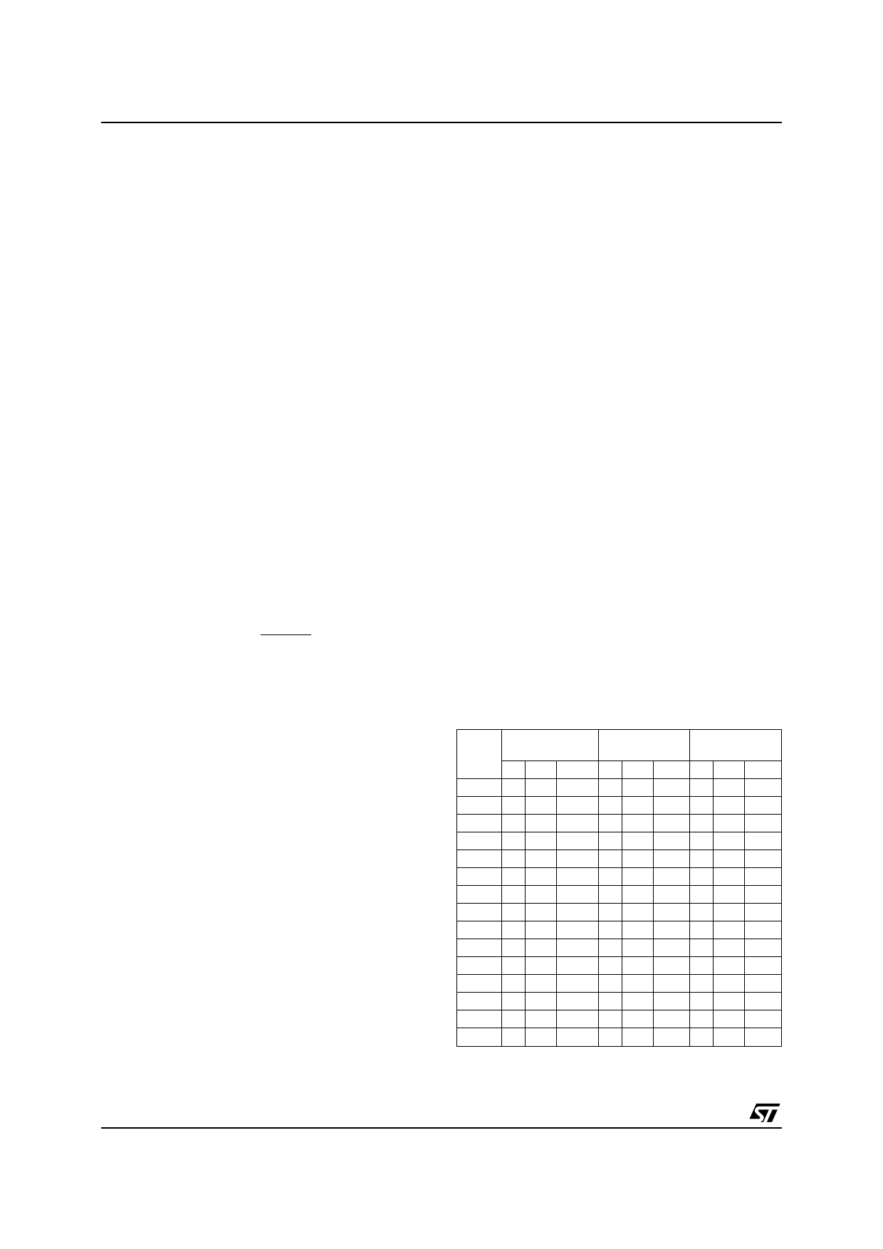
56 Kbps sampling frequencies (see Table 1).
When MCM = 0, the MCLK must be equal to the
oversampling frequency : Fs x OVER (7546 mode).
The ADC and DAC are oversampled at the OCLK
frequency. OCLK is equal to the shift clock used in
the serial interface.
The MCLK frequency should be :
MCLK = K x Sampling frequency
Combination of M, Q and oversampling ratios al-
lows to generate several sampling frequencies.
Recommended values for classical modem appli-
cations are as follow :
Table 1 : Sampling Frequencies Generation
F
(kHz)
16.00
13.96
13.71
12.80
12.00
11.82
10.97
10.47
10.29
9.60
9.00
8.86
8.23
8.00
7.20
FQ =
36.864MHz (1)
M Q over
3 6 128
3 5.5 160
3 7 128
3 6 160
3 8 128
3 6.5 160
3 7 160
4 5.5 160
4 7 128
4 6 160
4 8 128
4 6.5 160
4 7 160
4 6 192
4 8 160
FQ =
18.432MHz
M Q over
2 4.5 128
-- -
1 7 192
2 4.5 160
2 6 128
-- -
-- -
2 5.5 160
2 7 128
2 6 160
2 8 128
2 6.5 160
2 7 160
2 6 192
2 8 160
FQ =
9.216MHz
M Q over
1 6 96
-- -
1 7 96
1 4.5 160
1 6 128
-- -
-- -
1 5.5 160
1 7 128
1 6 160
1 8 128
1 6.5 160
1 7 160
1 6 192
1 8 160
Note : 1. Recommended value.
6/17
Share Link: 