1N6289CA 查看數據表(PDF) - Daesan Electronics Corp.
零件编号
产品描述 (功能)
生产厂家
1N6289CA Datasheet PDF : 6 Pages
| |||
1.5KE SERIES AND 1N6267 THRU 1N6303(C)A
POWER 1500Watts
VOLTAGE 6.8 to 440 Volts
Features
· Underwriters Laboratory recognition under UL standard
for safety 497B : Isolated loop circuit protection
· Glass passivated junction
· 1500W peak pulse power capability on 10/1000μS
waveform, repetition rate(duty cycle) : 0.05%
· Excellent clamping capability
· Low incremental surge resistance
· Very fast response time
· Includes 1N6267 thru 1N6303A
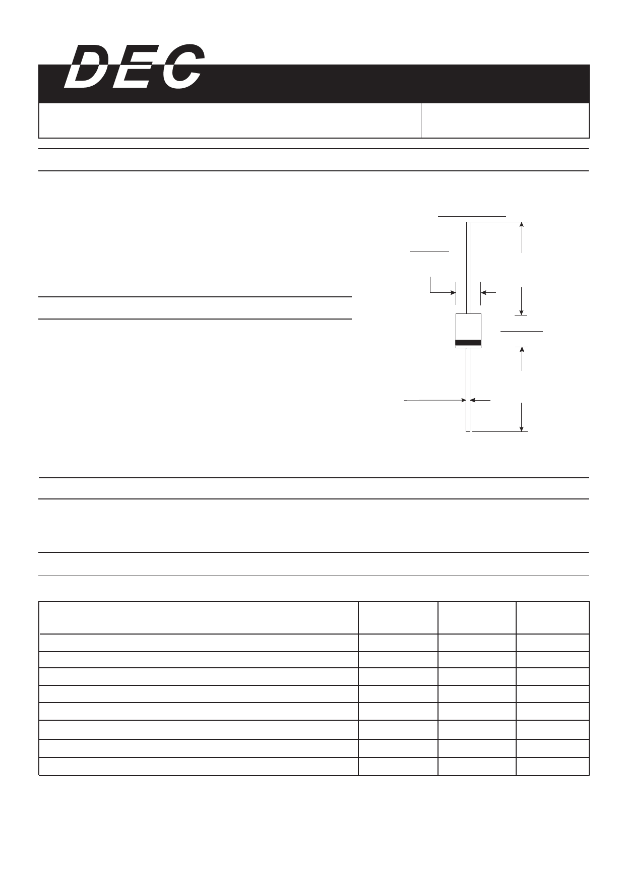
DO-201AD
0.210(5.3)
0.188(4.8)
DIA.
1.0(25.4)
MIN.
Mechanical Data
· Case : JEDEC DO-201AD molded plastic body
over passivated junction
· Terminals : Solder plated axial leads, solderable per
MIL-STD-750, method 2026
· High temperature soldering guaranteed : 265℃/10 seconds,
0.375"(9.5mm) lead length, 5lbs. (2.3Kg) tension
· Polarity : For uni-directional types the color band denotes
cathode, which is positive with respect to the
anode under normal TVS operation
· Mounting Position : Any
· Weight : 0.042 ounce, 0.18 gram
· Flammability : Epoxy is rated UL 94V-0
0.375(9.5)
0.285(7.2)
0.042(1.1)
0.037(0.9)
DIA.
1.0(25.4)
MIN.
Dimensions in inches and (millimeters)
Devices For Bidirectional Applications
· For bi-directional use C or CA suffix for types 1.5KE6.8 thru types K1.5E440(e.g. 1.5KE6.8C, 1.5KE440CA),
electrical characteristics apply in both directions.
Maximum Ratings And Electrical Characteristics
(Ratings at 25℃ ambient temperature unless otherwise specified)
Peak power dissipation with a 10/1000μS waveform (Note 1. Fig. 1)
Peak pulse current with a 10/1000μS waveform (Note 1)
Steady state power dissipation at TL=75℃ lead length 0.375"(9.5mm) (Note2)
Peak forward surge current, 8.3mm single half sine-wave unidirectional only (Note 3)
Maximum instantaneous forward voltage at 100A for unidirectional only (Note4)
Typical thermal resistance junction to lead
Typical thermal resistance junction to ambient
Operating junction and storage temperature range
Symbols
PPPM
IPPM
PM(AV)
IFSM
VF
RθJL
RθJA
TJ,TSTG
Values
1500
See next table
6.5
200
3.5/5.0
20
75
-55 to +175
Notes:
(1) Non repetitive current pulse, per Fig.3 and derated above TA=25℃ per Fig.2
(2) Mounted on copper pads area of 1.6×1.6"(40×40mm) per Fig.5
(3) Measured on 8.3ms single half sine-wave or equivalent square wave, duty cycle=4 pulse per minute maximum
(4) VF=3.5 Volts for 1.5KE220(A) & below; VF=5.0 Volts for 1.5KE250(A) & above
Units
Watts
Amps
Watts
Amps
Volts
℃/W
℃/W
℃
Share Link: 