1809C 查看數據表(PDF) - Maxim Integrated
零件编号
产品描述 (功能)
生产厂家
1809C Datasheet PDF : 10 Pages
| |||
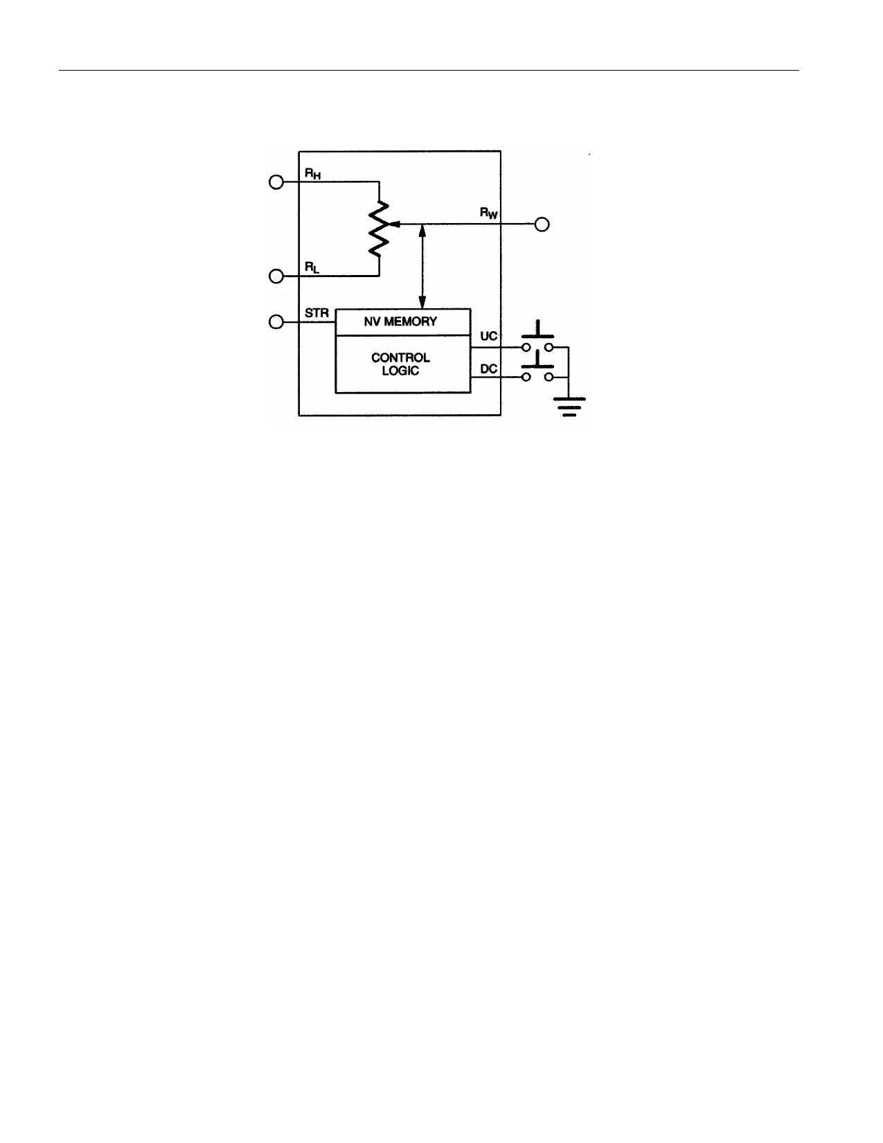
BLOCK DIAGRAM Figure 1
DS1809
OPERATION
The DS1809 Dallastat is a digitally controlled, nonvolatile potentiometer. A block diagram of the
DS1809 is shown in Figure 1. The DS1809 is a linear potentiometer providing 64-uniform wiper
positions over the entire resistor range including the end-terminals. All three potentiometer terminals of
the device are accessible. These terminals include RH, RL, and RW. RH and RL are the end-terminals of the
potentiometer. These terminals will have a constant resistance between them as defined by the
potentiometer value chosen: 10kΩ, 50kΩ, or the 100kΩ version. Functionally, RH and RL are
interchangeable. The wiper terminal, RW, is the multiplexed terminal and can be set to one of the 64 total
positions that exist on the resistor ladder including the RH and RL terminals.
Control of the wiper (RW) position setting is accomplished via the two inputs UC and DC. The UC and
DC control inputs, when active, determine the direction on the resistor array that the wiper position will
move. The UC (up control) control input is used to move the wiper position towards the RH terminal. The
DC (down control) control input is used to move wiper position towards the RL terminal.
The control inputs UC and DC are active low inputs that interpret input pulse widths as the means of
controlling wiper movement. Internally, these inputs are pulled up to VCC via a 100kΩ resistance. A
transition from a high-to-low on these inputs is considered the beginning of pulse input activity.
A single pulse on the UC or DC input is defined as being greater than 1 millisecond but lasting no longer
that ½ second. This type pulse input will cause the wiper position of the Dallastat to move one position.
Multiple pulse inputs (repetitive pulse inputs) can be used to step through each wiper position of the
device. The requirement for a repetitive pulse train on the UC or DC inputs is that pulses must be
separated by a minimum high time of 1ms. If this is not the case the Dallastat will ignore that pulse input.
A continuous pulse input (“push and hold”) is defined as lasting longer that one-half second. A
continuous pulse input will cause the wiper position to move one position every 100 milliseconds
following the initial one-half-second hold time. The total time to transcend the entire potentiometer given
a continuous pulse input is provided by the equation:
2 of 10
Share Link: 