3N60A4 查看數據表(PDF) - Intersil
零件编号
产品描述 (功能)
生产厂家
3N60A4 Datasheet PDF : 10 Pages
| |||
HGTD3N60A4S, HGT1S3N60A4S, HGTP3N60A4
Electrical Specifications TJ = 25oC, Unless Otherwise Specified (Continued)
PARAMETER
SYMBOL
TEST CONDITIONS
MIN TYP MAX UNITS
Current Turn-On Delay Time
Current Rise Time
Current Turn-Off Delay Time
Current Fall Time
Turn-On Energy (Note 3)
td(ON)I
trI
td(OFF)I
tfI
EON1
IGBT and Diode at TJ = 125oC
ICE = 3A
VCE = 390V
VGE = 15V
RG = 50Ω
L = 1mH
Test Circuit - Figure 20
-
5.5
8
ns
-
12
15
ns
-
110
165
ns
-
70
100
ns
-
37
-
µJ
Turn-On Energy (Note 3)
EON2
-
90
100
µJ
Turn-Off Energy (Note 2)
Thermal Resistance Junction To Case
EOFF
RθJC
-
50
80
µJ
-
-
1.8
oC/W
NOTES:
2. Turn-Off Energy Loss (EOFF) is defined as the integral of the instantaneous power loss starting at the trailing edge of the input pulse and ending
at the point where the collector current equals zero (ICE = 0A). All devices were tested per JEDEC Standard No. 24-1 Method for Measurement
of Power Device Turn-Off Switching Loss. This test method produces the true total Turn-Off Energy Loss.
3. Values for two Turn-On loss conditions are shown for the convenience of the circuit designer. EON1 is the turn-on loss of the IGBT only. EON2
is the turn-on loss when a typical diode is used in the test circuit and the diode is at the same TJ as the IGBT. The diode type is specified in
Figure 20.
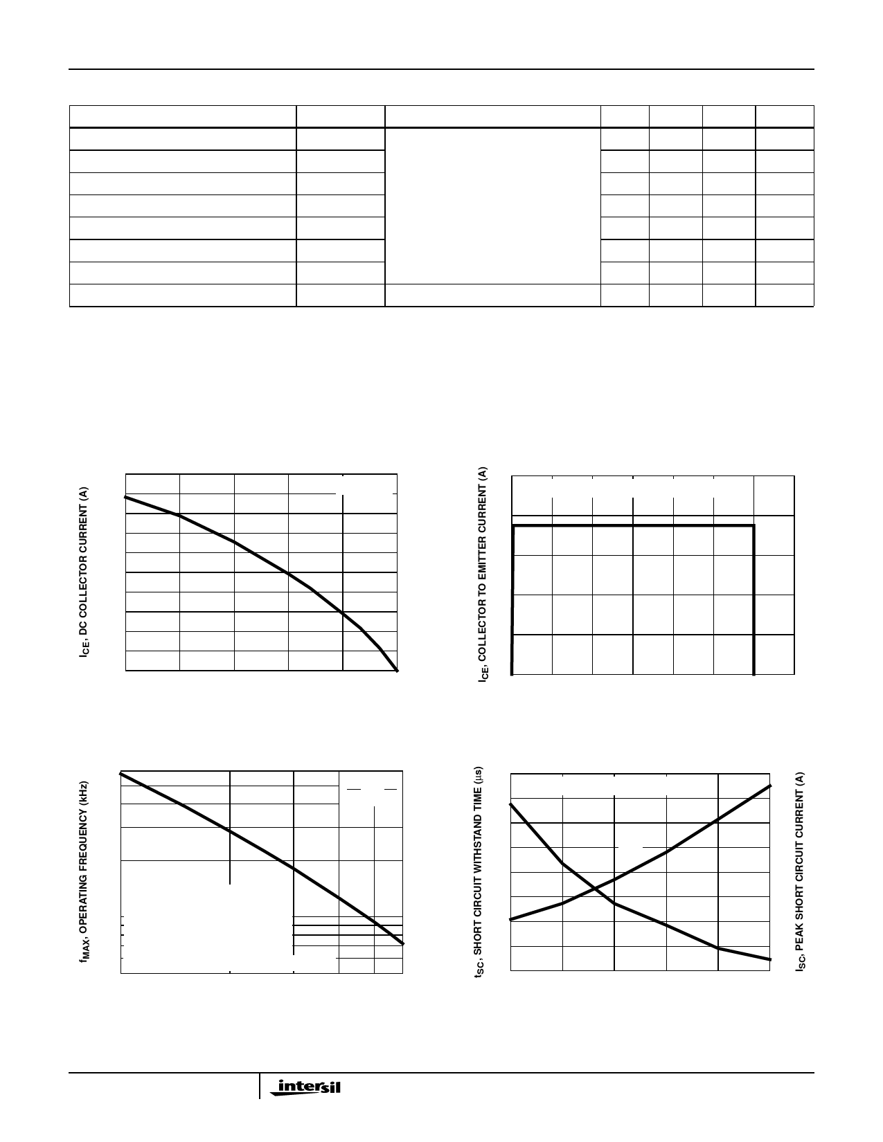
Typical Performance Curves Unless Otherwise Specified
20
20
VGE = 15V
TJ = 150oC, RG = 50Ω, VGE = 15V, L = 200µH
16
16
12
12
8
8
4
4
0
25
50
75
100
125
150
TC, CASE TEMPERATURE (oC)
FIGURE 1. DC COLLECTOR CURRENT vs CASE
TEMPERATURE
600
TC VGE
75oC 15V
300
200
fMAX1 = 0.05 / (td(OFF)I + td(ON)I)
fMAX2 = (PD - PC) / (EON2 + EOFF)
100 PC = CONDUCTION DISSIPATION
(DUTY FACTOR = 50%)
RØJC = 1.8oC/W, SEE NOTES
TJ = 125oC, RG = 50Ω, L = 1mH, VCE = 390V
50
1
2
3
4
56
ICE, COLLECTOR TO EMITTER CURRENT (A)
FIGURE 3. OPERATING FREQUENCY vs COLLECTOR TO
EMITTER CURRENT
0
0
100 200 300 400 500 600 700
VCE, COLLECTOR TO EMITTER VOLTAGE (V)
FIGURE 2. MINIMUM SWITCHING SAFE OPERATING AREA
20
64
VCE = 390V, RG = 50Ω, TJ = 125oC
18
56
tSC
16
48
14
40
ISC
12
32
10
24
8
16
6
8
4
0
10
11
12
13
14
15
VGE, GATE TO EMITTER VOLTAGE (V)
FIGURE 4. SHORT CIRCUIT WITHSTAND TIME
3
Share Link: 