MAX6603 查看數據表(PDF) - Maxim Integrated
零件编号
产品描述 (功能)
生产厂家
MAX6603 Datasheet PDF : 9 Pages
| |||
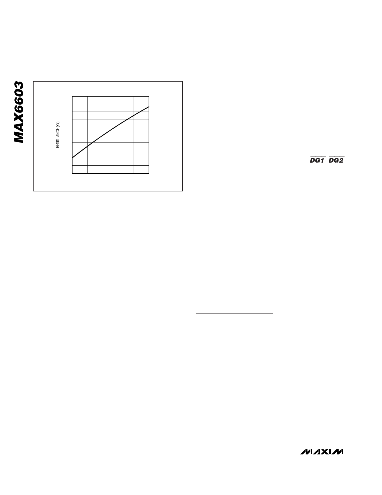
Dual-Channel, Platinum RTD-to-Voltage
Signal Conditioner
1000
900
800
700
600
500
400
300
200
100
0
0
200Ω Pt RTD
200 400 600 800 1000
TEMPERATURE (°C)
Figure 1. Typical 200Ω Pt RTD Representation by the
Simplified Callender-Van Dusen Equation
microcontrollers that incorporate an ADC and enables a
low-cost, low-complexity solution. Ratiometricity is an
important consideration for battery-operated instru-
ments, automotive, and some industrial applications.
Temperature Information
The MAX6603 measures the resistance between the
RTD and translates that into a high-level output voltage.
The resistance range of the MAX6603 is between 150Ω
and 900Ω, covering a -40°C to +1000°C temperature
range. When R(T) goes too low or too high, a fault con-
dition is asserted and the respective DG_ goes low.
Output Voltage
The following equation describes the output voltage:
where:
VOUT
=
VCC × R(T)
1000
VCC = supply voltage
R(T) = RTD resistance given by Callendar-
Van Dusen equation.
Using Other Pt RTDs
The MAX6603 is designed for a 200Ω Pt RTD, but the
device can work with any RTD as long as the resistance
is in the 150Ω to 900Ω range. A 500Ω Pt RTD can be
used for temperatures up to +208°C because that tem-
perature results in R(T) = 900Ω.
Input Overvoltage Protection to +16V
The input pins RS1+, RS1-, RS2+, and RS2- protect the
MAX6603 from overvoltage conditions up to +16V with-
out damaging the device.
Diagnostic Outputs (DG1, DG2)
The MAX6603 continuously monitors the excitation
current to the RTD, the resultant voltage drop, and
voltage levels of the inputs to detect fault conditions.
Any fault condition causes the respective DG output to
assert low. Fault conditions occur for RTD open circuits;
RTD short circuits; and RS1+, RS1-, RS2+, and RS2-
short to ground or supply. If any fault is detected, the
respective DG output asserts low. OUT1 and OUT2 are
high impedance on assertion of DG1 and DG2, respec-
tively. An example circuit showing potential fault condi-
tions is shown in Figure 2.
Applications Information
Ratiometric Output Coupled to a
Microcontroller
The circuit of Figure 3 shows the MAX6603 connected to
the microcontroller using VCC as the ADC reference volt-
age. The output is ratiometric to VCC, and temperature
measurements are independent of the supply voltage.
PROCESS: BiCMOS
Chip Information
6 _______________________________________________________________________________________
Share Link: 