UTCTEA1062A 查看數據表(PDF) - Unisonic Technologies
零件编号
产品描述 (功能)
生产厂家
UTCTEA1062A Datasheet PDF : 13 Pages
| |||
UTCTEA1062/1062A LINEARINTEGRATEDCIRCUIT
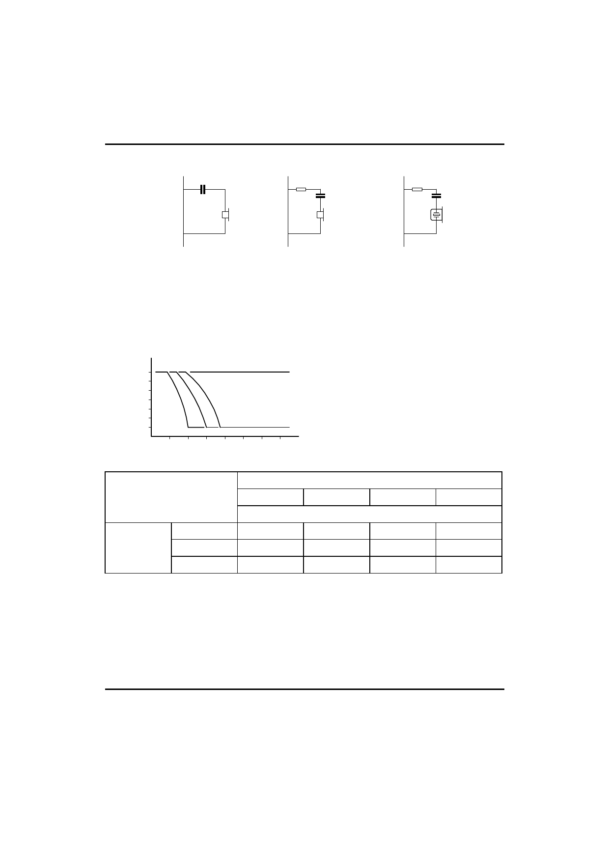
QR 4
QR 4 (1)
QR 4 (2)
VEE 9
VEE 9
VEE 9
(a)
(b)
(c)
Fig.11 Alternative receiver arrangement
(a) Dynamic earpiece.
(b) Magnetic earpiece.The resistor marked(1) may be connected to prvent distortion(inductive load)
(c) Piezoelectric earpiece.The earpiece marked(2) is requirred to increase the phase margin (capacitive load)
Fig.12 Variation of gain with line urrent,with R6 as a parameter.
¡÷Gv
(dB)
0
R6=¡Þ
-2
R9=20Ω
-4
(1) (2) (3)
-6
(1) R6= 78.7kΩ
(2) R6= 110kΩ
(3) R6= 140kΩ
0 20 40 60 80 100 120 140
Iline (mA)
Rexch(Ω)
400
600
800
1000
R6(kΩ)
36
100
78.7
¡Á
¡Á
Vexch(V)
48
140
110
93.1
82
60
¡Á
¡Á
120
102
Table 1 Values of resistor R6 for optimum line loss compensation,for various usual values of exchange
supply vloltage(Vexch) and exchange feeding bridge resistance(Rexch);R9=20Ω.
UTC UNISONIC TECHNOLOGIES CO., LTD. 11
QW-R108-001,A
Share Link: 