ST103S 查看數據表(PDF) - International Rectifier
零件编号
产品描述 (功能)
生产厂家
ST103S Datasheet PDF : 10 Pages
| |||
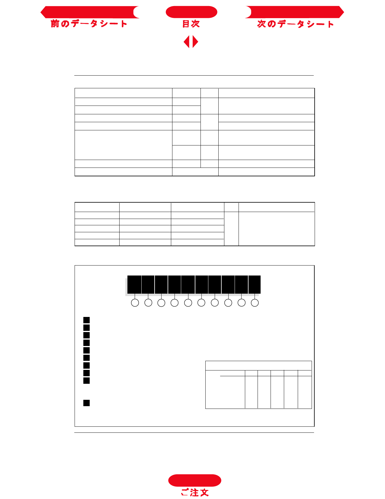
Previous Datasheet
Index
Next Data Sheet
ST103S Series
Thermal and Mechanical Specifications
Parameter
ST103S Units Conditions
TJ
Tstg
RthJC
RthCS
T
Max. junction operating temperature range
Max. storage temperature range
Max. thermal resistance, junction to case
Max. thermal resistance, case to heatsink
Mounting torque, ± 10%
wt Approximate weight
Case style
-40 to 125
°C
-40 to 150
0.195
K/W
0.08
15.5
(137)
Nm
(Ibf-in)
14
(120)
Nm
(Ibf-in)
130
g
TO-209AC (TO-94)
DC operation
Mounting surface, smooth, flat and greased
Non lubricated threads
Lubricated threads
See Outline Table
∆RthJC Conduction
(The following table shows the increment of thermal resistence RthJC when devices operate at different conduction angles than DC)
Conduction angle Sinusoidal conduction Rectangular conduction Units Conditions
180°
120°
90°
60°
30°
0.034
0.040
0.052
0.076
0.126
0.025
0.042
0.056
0.079
0.127
K/W
TJ = TJ max.
Ordering Information Table
Device Code
ST 10 3 S 08 P F N 0
1 2 3 4 5 6 7 8 9 10
1 - Thyristor
2 - Essential part number
3 - 3 = Fast turn off
4 - S = Compression bonding Stud
5 - Voltage code: Code x 100 = VRRM (See Voltage Ratings table)
6 - P = Stud Base 1/2" 20UNF
7 - Reapplied dv/dt code (for tq test condition)
dv/dt - tq combinations available
8 - tq code
dv/dt (V/µs) 20 50 100 200 400
9 - 0 = Eyelet terminals (Gate and Aux. Cathode Leads)
10
CN DN EN FN * --
12
CM DM EM FM HM
1 = Fast-on terminals (Gate and Aux. Cathode Leads)
15
2 = Flag terminals (For Cathode and Gate Terminals) tq(µs) 18
CL DL EL FL * HL
CP DP EP FP HP
10 - Critical dv/dt:
20
CK DK EK FK HK
25
-- -- -- -- HJ
None = 500V/µsec (Standard value)
*Standard part number.
L
= 1000V/µsec (Special selection)
All other types available only on request.
D-444
To Order
Share Link: 