MAX703 查看數據表(PDF) - Maxim Integrated
零件编号
产品描述 (功能)
生产厂家
MAX703 Datasheet PDF : 10 Pages
| |||
MAX703/MAX704
Low-Cost Microprocessor Supervisory
Circuits with Battery Backup
Detailed Description
RESET Output
A μP’s reset input starts the μP in a known state.
Whenever the μP is in an unknown state, it should be held
in reset. The MAX703/MAX704 assert reset when VCC is
low, preventing code-execution errors during power-up,
power-down, or brownout conditions.
When VBATT is 2V or more, RESET is always valid,
irrespective of VCC. On power-up, as VCC rises, RESET
remains low. When VCC exceeds the reset threshold, an
internal timer holds RESET low for a time equal to the
reset pulse width (typically 200ms); after this interval,
RESET goes high (Figure 2). If a power-fail or brown-
out condition occurs (i.e., VCC drops below the reset
threshold), RESET is asserted. As long as VCC remains
below the reset threshold, the internal timer is continually
restarted, causing the RESET output to remain low. Thus,
a brownout condition that interrupts a previously initiated
reset pulse causes an additional 200ms delay from the
end of the last interruption.
Power-Fail Comparator
The PFI input is compared to an internal reference. If PFI
is less than 1.25V, PFO goes low. The power-fail com-
parator can be used as an undervoltage detector to signal
a failing power supply. In the Typical Operating Circuit,
an external voltage-divider at PFI is used to monitor the
unregulated DC voltage from which the regulated +5V
supply is derived.
The voltage-divider can be chosen so the voltage at PFI falls
below 1.25V just before the +5V regulator drops out. PFO is
then used as an interrupt to prepare the μP for power-down.
To conserve power, the power-fail comparator is turned off
and PFO is forced low when the MAX703/MAX704 enter
battery-backup mode.
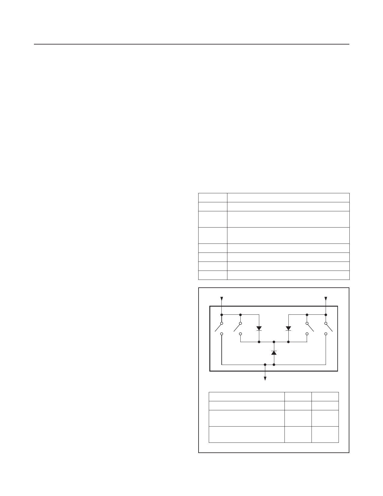
Backup-Battery Switchover
In the event of a brownout or power failure, it may be nec-
essary to preserve the contents of RAM. With a backup
battery installed at VBATT, the MAX703/MAX704 auto-
matically switch RAM to backup power when VCC fails.
As long as VCC exceeds the reset threshold, VCC con-
nects to VOUT through a 5Ω p-channel MOSFET power
switch. Once VCC falls below the reset threshold, RESET
goes low and VCC or VBATT (whichever is higher) switch-
es to VOUT. Note that VBATT switches to VOUT through
an 80Ω switch only if VCC is below the resetthreshold volt-
age and VBATT is greater than VCC. When VCC exceeds
the reset threshold, it is connected to the MAX703/
MAX704 substrate, regardless of the voltage applied to
VBATT (Figure 3). During this time, diode D1 (between
VBATT and the substrate) conducts current from VBATT to
VCC if VBATT ≥ (VCC + 0.6V).
When the battery-backup mode is activated, VBATT con-
nects to VOUT. In this mode, the substrate connects to
VBATT and internal circuitry is powered from the battery
(Figure 3). Table 1 shows the status of the MAX703/
MAX704 inputs and outputs in battery-backup mode.
When VCC is below, but within, 1V of VBATT, the internal
switchover comparator draws about 30μA. Once VCC
Table 1. Input and Output Status in
Battery-Backup Mode
SIGNAL
VCC
VOUT
VBATT
RESET
PFI
PFO
MR
STATUS
Disconnected from VOUT.
Connected to VBATT through an internal 80Ω
p-channel MOSFET switch.
Connected to VOUT. Supply current is < 1µA
when VCC < (VBATT - 1V).
Logic-low.
Power-fail comparator is disabled.
Logic-low.
Disabled.
VBATT
VCC
MAX703
S1
S2
MAX704
S3
S4
D1
D2
SUBSTRATE
D3
VOUT
CONDITION
VCC > Reset Threshold
VCC < Reset Threshold and
VCC > VBATT
VCC < Reset Threshold and
VCC < VBATT
S1/S2
Open
Open
S1/S2
Closed
Closed
Closed Open
Figure 3. Battery-Switchover Block Diagram
www.maximintegrated.com
Maxim Integrated │ 5
Share Link: 