FPF2123 查看數據表(PDF) - ON Semiconductor
零件编号
产品描述 (功能)
生产厂家
FPF2123 Datasheet PDF : 15 Pages
| |||
Application Information
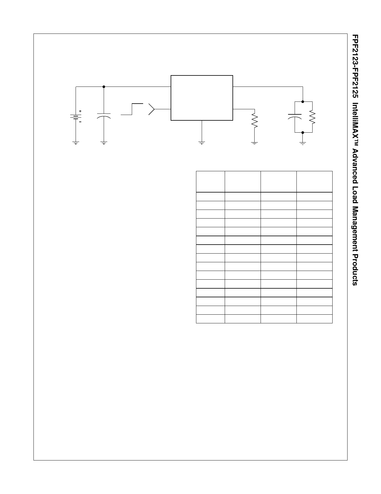
Typical Application
Battery
5.5V
OFF ON
C1=4.7 F
5.5V MAX
VIN
VOUT
FPF2123- FPF2125
ON
ISET
GND
RSET
C2=0.1 F
R2=110
Setting Current Limit
The FPF2123, FPF2124, and FPF2125 have a current limit
which is set with an external resistor connected between ISET
and GND. This resistor is selected by using the following
equation,
RSET
=
4----6---0--
ILIM
RSET is in Ohms and that of ILIM is Amps
The table below can also be used to select RSET. A typical
application would be the 500mA current that is required by a
single USB port. Using the table below an appropriate selection
for the RSET resistor would be 604 . This will ensure that the
port load could draw 570mA, but not more than 950mA.
Likewise for a dual port system, an RSET of 340 would always
deliver at least 1120mA and never more than 1860mA.
Input Capacitor
To limit the voltage drop on the input supply caused by transient
in-rush currents when the switch turns-on into a discharged load
capacitance or a short-circuit, a capacitor needs to be placed
between VIN and GND. A 4.7 F ceramic capacitor, CIN, must be
placed close to the VIN pin. A higher value of CIN can be used to
further reduce the voltage drop experienced as the switch is
turned on into a large capacitive load.
Output Capacitor
A 0.1 F capacitor, COUT, should be placed between VOUT and
GND. This capacitor will prevent parasitic board inductances
from forcing VOUT below GND when the switch turns-off. For the
FPF2123 and FPF2124, the total output capacitance needs to
be kept below a maximum value, COUT(max), to prevent the part
from registering an over-current condition and turning-off the
switch. The maximum output capacitance can be determined
from the following formula,
COUT(max)
=
ILIM(min) × tBLANK(min)
-----------------------------V----I-N------------------------------
Current Limit Various RSET Values
RSET
[]
Min. Current Typ. Current Max. Current
Limit
Limit
Limit
[mA]
[mA]
[mA]
309
1120
1490
1860
340
1010
1350
1690
374
920
1230
1540
412
840
1120
1400
453
760
1010
1270
499
690
920
1150
549
630
840
1050
576
600
800
1000
604
570
760
950
732
470
630
790
887
390
520
650
1070
320
430
540
1300
260
350
440
1910
180
240
300
3090
110
150
190
Power Dissipation
During normal operation as a switch, the power dissipated in the
part will depend upon the level at which the current limit is set.
The maximum allowed setting for the current limit is 1.5A and
this will result in a typical power dissipation of,
P = (ILIM)2 × RON = (1.5)2 × 0.125 = 281mW
If the part goes into current limit the maximum power dissipation
will occur when the output is shorted to ground. For the
FPF2123 the power dissipation will scale by the Auto-Restart
Time, tRESTART, and the Over Current Blanking Time, tBLANK, so
that the maximum power dissipated is,
P(max)=
tBLANK(max)
-t-R----E---S---T---A---R----T---(--m------i--n---)----+-----t--B---L---A---N---K----(--m-----a----x----)
×
VIN(
m
a
x)
×
ILIM(
m
ax
)
(4)
=
20
8----0-----+-----2---0--
× 5.5 × 1.5
=
1.65 W
10
FPF2123-FPF2125 Rev. F
www.fairchildsemi.com
Share Link: 