BFS17AW 查看數據表(PDF) - Vishay Semiconductors
零件编号
产品描述 (功能)
生产厂家
BFS17AW Datasheet PDF : 10 Pages
| |||
BFS17A / BFS17AR / BFS17AW
Vishay Semiconductors
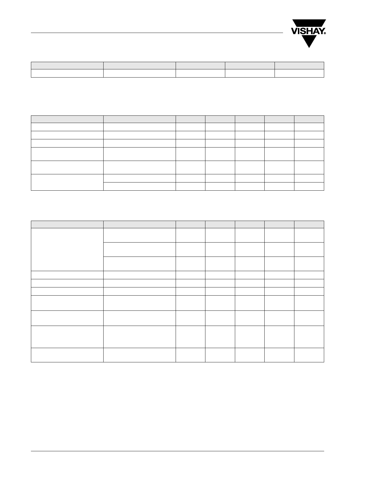
Maximum Thermal Resistance
Parameter
Junction ambient
Test condition
1)
1) on glass fibre printed board (25 x 20 x 1.5) mm3 plated with 35 μm Cu
Symbol
RthJA
Electrical DC Characteristics
Tamb = 25 °C, unless otherwise specified
Parameter
Test condition
Collector-emitter cut-off current VCE = 25 V, VBE = 0
Collector-base cut-off current VCB = 10 V, IE = 0
Emitter-base cut-off current
VEB = 2.5 V, IC = 0
Collector-emitter breakdown
voltage
IC = 1 mA, IB = 0
Collector-emitter saturation
voltage
IC = 20 mA, IB = 2 mA
DC forward current transfer ratio VCE = 1 V, IC = 2 mA
VCE = 1 V, IC = 25 mA
Symbol
Min
ICES
ICBO
IEBO
V(BR)CEO
15
VCEsat
hFE
20
hFE
20
Electrical AC Characteristics
Tamb = 25 °C, unless otherwise specified
Parameter
Test condition
Symbol
Min
Transition frequency
VCE = 5 V, IC = 2 mA,
fT
f = 300 MHz
VCE = 5 V, IC = 14 mA,
fT
f = 300 MHz
VCE = 5 V, IC = 30 mA,
f = 300 MHz
fT
3
Collector-base capacitance
VCB = 10 V, f = 1 MHz
Ccb
Collector-emitter capacitance VCE = 5 V, f = 1 MHz
Cce
Emitter-base capacitance
VEB = 0.5 V, f = 1 MHz
Ceb
Noise figure
VCE = 5 V, IC = 2 mA,
F
ZS = 50 Ω, f = 800 MHz
Power gain
VCE = 10 V, IC = 14 mA,
Gpe
ZS = 50 Ω, f = 800 MHz
Linear output voltage - two tone
intermodulation test
VCE = 10 V, IC = 14 mA,
dIM = 60 dB, f1 = 806 MHz,
f2 = 810 MHz, ZS = ZL = 50 Ω
V1 = V2
Third order intercept point
VCE = 10 V, IC = 14 mA,
IP3
f = 800 MHz
Value
450
Typ.
0.1
100
Typ.
1.5
3.5
3.2
0.6
0.1
1.1
2.5
13
150
23.5
Unit
K/W
Max
Unit
100
μA
100
nA
10
μA
V
0.6
V
150
Max
Unit
GHz
GHz
GHz
pF
pF
pF
dB
dB
mV
dBm
www.vishay.com
2
Document Number 85039
Rev. 1.6, 08-Sep-08
Share Link: 