TR8100 查看數據表(PDF) - Murata Manufacturing
零件编号
产品描述 (功能)
生产厂家
TR8100 Datasheet PDF : 15 Pages
| |||
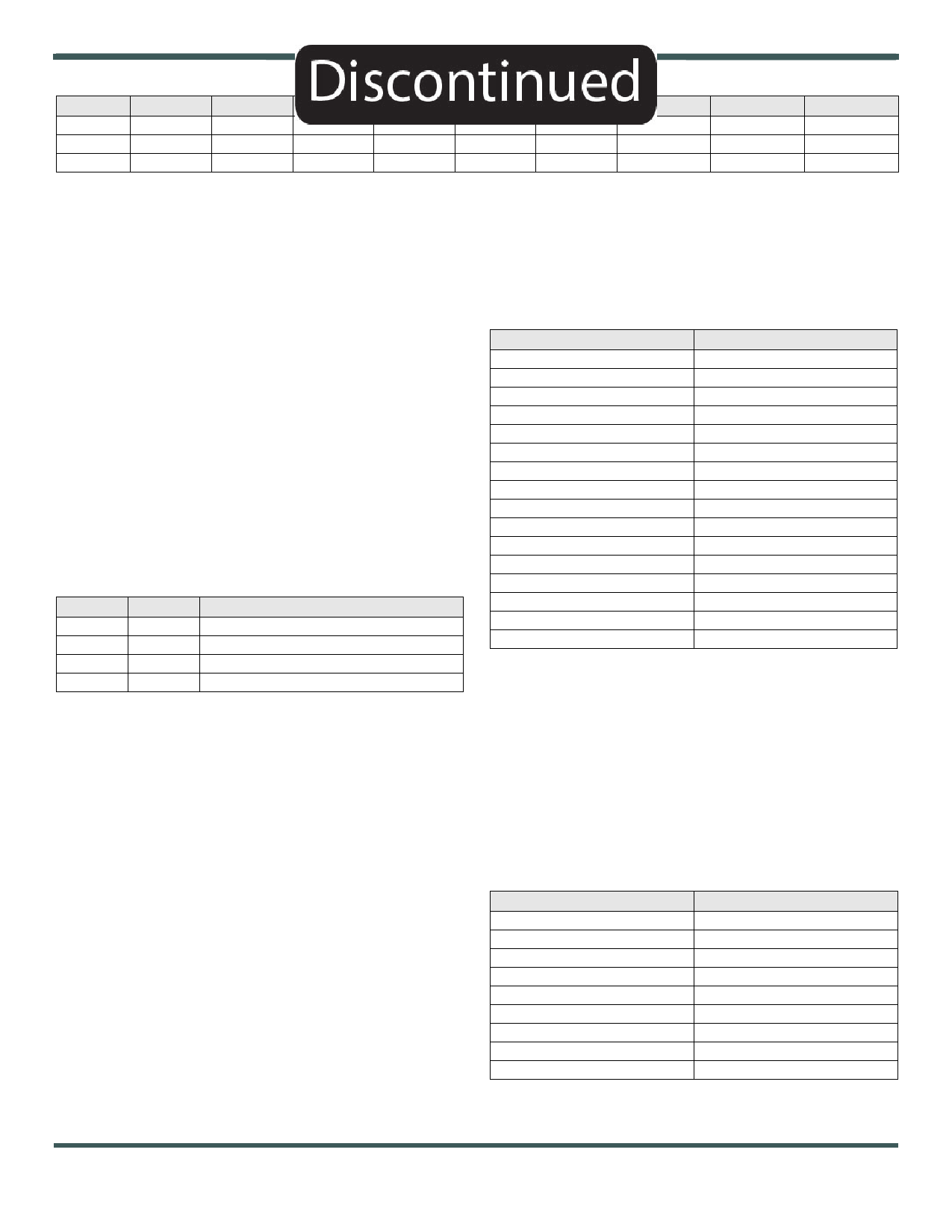
Adress
0
1
2
Name
CFG0
CFG1
LoSyn
Bit 7
Sleep
-
Test
Bit 6
TX/RX
VCOlock
LOSyn6
Bit 5
Bit 4
ASK/OOK
-
ISSMod
-
LOSyn5
LOSyn4
Figure 3
Bit 3
Mode 1
BR3
LOSyn3
Bit 2
Mode 0
BR2
LOSyn2
Bit 1
-
BR1
LOSyn1
Bit 0
SV En
BR0
LOSyn0
CFG0 Bit 7 - When this bit is 0, the radio is operational. Setting this
bit to 1 invokes the sleep mode. In the sleep mode most of the
radio is powered down, reducing the radio’s current consumption
to about 200 nA. The contents of the configuration registers are
preserved during sleep mode. The power-on default value of this
bit is 0. Note that once sleep mode is invoked, Pin 19 must be set
to a logic 1 to return to active operation. In changing from sleep
mode to active mode, Pin 19 should be high for at least one
microsecond before attempting to clock data in or out of the control
registers.
CFG0 Bit 6 - When this bit is 0, the radio is in the receive mode
(provided CFG0 Bit 7 is 0). When this bit is 1, the radio is in one of
the transmit modes. Note the radio will transmit using OOK or ASK
modulation, depending on the value of CFG0 Bit 5. The power-on
default value of this bit is 0.
CFG0 Bit 5 - When this bit is 0, the transmitter uses OOK modula-
tion. When this bit is 1, the transmitter uses ASK modulation. The
power-on default value of this bit is 0.
CFG0 Bit 4 - The power-on default value of this bit is 0. This bit
should always be set to 0 when operating the TR8100-1 in 3G
mode.
Bit 3
0
0
1
1
Bit 2
0
1
0
1
Mode
Single-channel Mode (Receive)
Not Used
Digital Modulation (DSSS) Transmit Mode
Not Used
CFG0 Bits 3, 2 - The states of these two bits set the basic operating
mode of the radio as shown below. The target transmit mode for
the TR8100-1 is “digital modulation” (DSSS), so Bit 3 should be set
to a logic 1 and Bit 2 should be set to a logic 0 each time a
transmission is made. The power-on default value of these two bits
is 0.
CFG0 Bit 1 - The power-on default value of this bit is 0, and should
always be set to 0 when operating the TR8100-1 in 3G mode.
CFG0 Bit 0 - Setting this bit to logic 1 enables the internal start
symbol (vector) detection and the data and clock recovery circuit.
When active, this function continuously tests for a 16-bit start
symbol, 0xE2E2 (hex). Data clocking begins in the middle of the
first bit following the 16-bit start symbol, and clocking continues
until CFG0 Bit 0 is reset to a logic 0. Note that CFG0 Bit 0 must be
set to back to a logic 1 to re-enable the start symbol detection and
the data and clock recovery circuit. The common way to use this
function is for the host processor to set this bit to 1 when it is ready
to receive a message. When a start symbol is detected, data
clocking begins, and the host processor inputs the message bits.
Once all of the bits in the message are received, the host
processor resets this bit to 0 to end data clocking. After the
message has been processed, the host processor sets this bit to 1
again to enable detection of the next message. The power-on
default value of this bit is 0.
The start symbol pattern is sent starting with the MSB. This start
symbol pattern will not occur in a message that has been encoded
for DC-balance using either Manchester encoding or 8-to-12 bit
symbolization using the encoding table given below. Note that the
table is given for 4-to-6 bit encoding, so each byte of the message
is encoded starting with the high nibble and then the low nibble.
Nibble Hex Value (4 bits)
0
1
2
3
4
5
6
7
8
9
A
B
C
D
E
F
Symbol Hex Value (6 bits)
0D
0E
13
15
16
19
1A
1C
23
25
26
29
2A
2C
32
34
CFG1 Bit 7 - This is a read-only bit that is not used by the TR8100-
1.
CFG1 Bit 6 - This bit is a Read Only bit. Writing has no effect.
When performing a read and this bit is set, this indicates that the
internal VCO is locked and ready to transmit or receive data.
CFG1 Bit 5 - When set to a logic 1, this bit selects a simple 460800
chip/s 1-0-1-0…DSSS “spreading code” designed to meet FCC
15.247 transmitter spectral density criteria. This bit should always
be set to 1 when operating the TR8100-1 in 3G mode.
CFG1 Bit 4 - This bit is unused in the TR8100-1.
CFG1 Bits 3, 2, 1, 0 - These bits select the internal data and clock
recovery data (bit) rate as shown in the table below. The power-on
default value of these bits is 0.
Data Rate (b/s)
1200
2400
4800
9600
19200
38400
57600
115200
230400
CFG1 Bits 3-0
0000
0001
0010
0011
0100
0101
0110
0111
1000
©2010-2015 by Murata Electronics N.A., Inc.
TR8100 (R) 4/24/15
Page 7 of 15
www.murata.com
Share Link: 