AMP04 查看數據表(PDF) - Analog Devices
零件编号
产品描述 (功能)
生产厂家
AMP04 Datasheet PDF : 17 Pages
| |||
AMP04
1mV
2s
100
90
10
0%
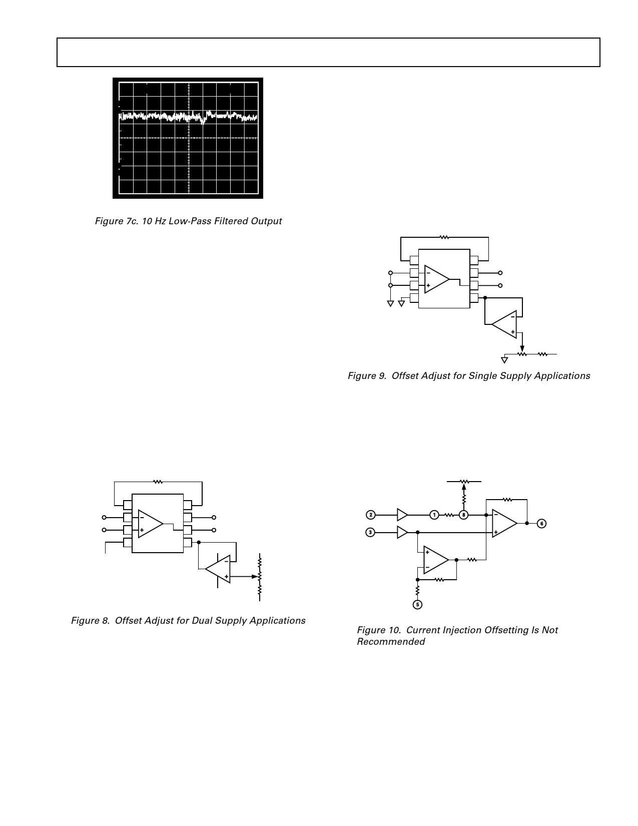
Figure 7c. 10 Hz Low-Pass Filtered Output
Power Supply Considerations
In dual supply applications (for example ± 15 V) if the input is
connected to a low resistance source less than 100 Ω, a large
current may flow in the input leads if the positive supply is
applied before the negative supply during power-up. A similar
condition may also result upon a loss of the negative supply. If
these conditions could be present in you system, it is recom-
mended that a series resistor up to 1 kΩ be added to the input
leads to limit the input current.
This condition can not occur in a single supply environment
as losing the negative supply effectively removes any current
return path.
Offset Nulling in Dual Supply
Offset may be nulled by feeding a correcting voltage at the VREF
pin (Pin 5). However, it is important that the pin be driven with
a low impedance source. Any measurable resistance will degrade
the amplifier’s common-mode rejection performance as well as
its gain accuracy. An op amp may be used to buffer the offset
null circuit as in Figure 8.
RG
–
INPUT
+
–5V
1
AMP04
8
2
V+ 7
3
6
4 V–
REF 5
*OP90 FOR LOW POWER
OP113 FOR LOW DRIFT
5V
OUTPUT
+5V
+5V
50k⍀
*
100⍀
؎5mV
–5V
ADJ
RANGE
50k⍀
–5V
Figure 8. Offset Adjust for Dual Supply Applications
Offset Nulling in Single Supply
Nulling the offset in single supply systems is difficult because
the adjustment is made to try to attain zero volts. At zero volts
out, the output is in saturation (to the negative rail) and the
output voltage is indistinguishable from the normal offset error.
Consequently the offset nulling circuit in Figure 9 must be used
with caution.
First, the potentiometer should be adjusted to cause the output
to swing in the positive direction; then adjust it in the reverse
direction, causing the output to swing toward ground, until
the output just stops changing. At that point the output is at
the saturation limit.
RG
INPUT
1
AMP04
8
2
7
5V
3
6
OUTPUT
4
5
OP113
5V
100⍀ 50k⍀
Figure 9. Offset Adjust for Single Supply Applications
Alternative Nulling Method
An alternative null correction technique is to inject an offset
current into the summing node of the output amplifier as in
Figure 10. This method does not require an external op amp.
However, the drawback is that the amplifier will move off its
null as the input common-mode voltage changes. It is a less
desirable nulling circuit than the previous method.
V+
IN(–)
IN(+)
RGAIN
INPUT BUFFERS
V–
100k⍀
VOUT
11k⍀
11k⍀
100k⍀
REF
Figure 10. Current Injection Offsetting Is Not
Recommended
REV. C
–9–
Share Link: 